Centrally located linear actuators for driving displacers in a thermodynamic apparatus

A technology for linear actuators and thermal equipment, applied in lighting and heating equipment, mechanical equipment, irreversible cycle compressors, etc., to achieve the effect of less chance of failure, easy assembly, and low friction

Active Publication Date: 2020-07-17
THERMOELEVATOR
View PDF16 Cites 0 Cited by
  • Summary
  • Abstract
  • Description
  • Claims
  • Application Information

AI Technical Summary

Problems solved by technology

This seal causes a

Method used


Image

  • Centrally located linear actuators for driving displacers in a thermodynamic apparatus
  • Centrally located linear actuators for driving displacers in a thermodynamic apparatus
  • Centrally located linear actuators for driving displacers in a thermodynamic apparatus

Examples


Example Embodiment

[0043] As will be understood by those of ordinary skill in the art, various features of the embodiments shown and described with reference to any one figure may be combined with features shown in one or more other figures to create alternatives not expressly shown or described Example. The combinations of features shown provide representative embodiments for typical applications. However, various combinations and modifications of the features consistent with the teachings of the present invention are contemplated for particular applications or implementations. Similar applications or implementations will be recognized by those of ordinary skill in the art, whether or not explicitly described or shown.
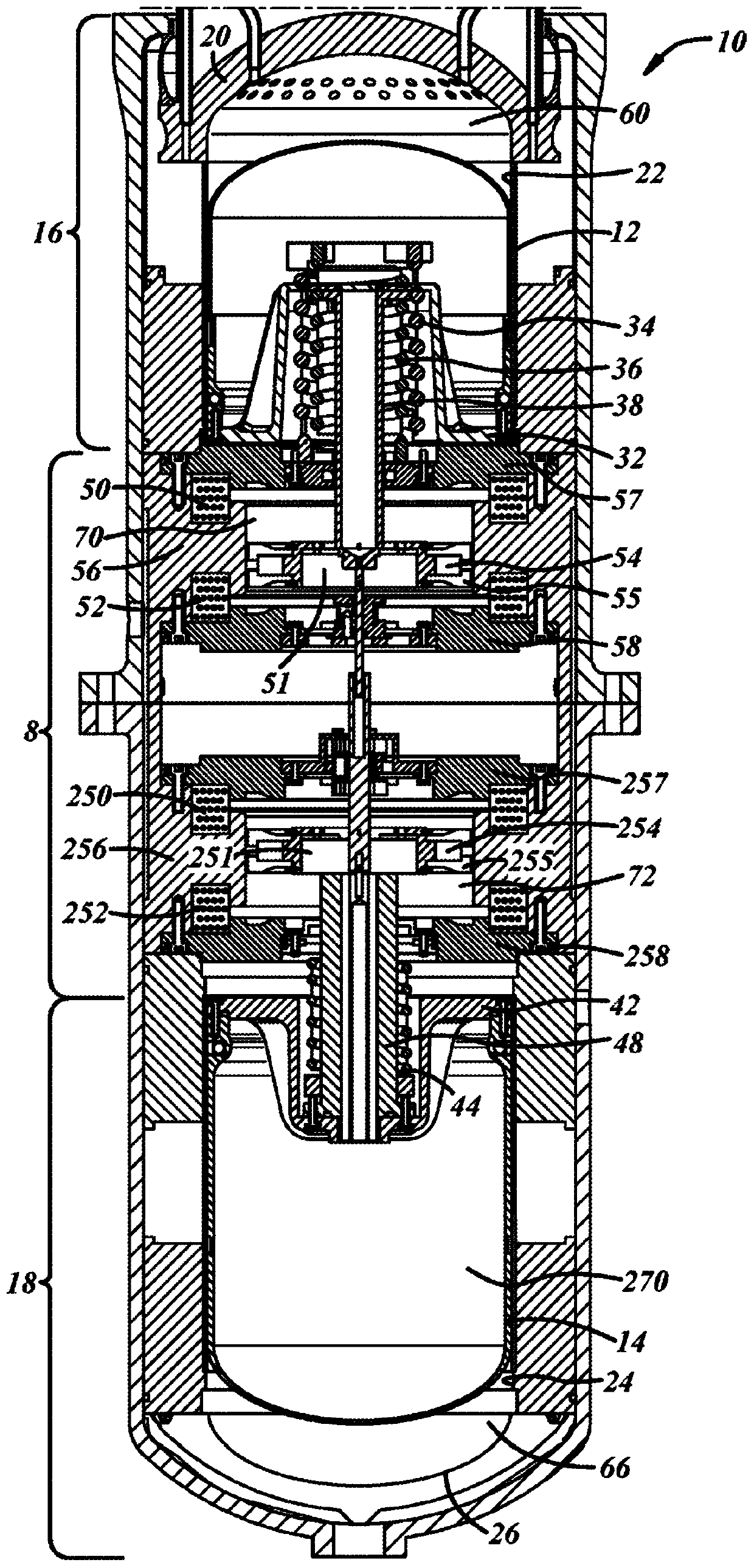
[0044] exist figure 2 In it, the heat pump 10 has a heat displacer portion 16 that includes the heat displacer 12 reciprocating within a heat displacer cylinder 22 . The heat pump 10 also has a cold displacer portion 18 that includes the cold displacer 14 reciprocating with...


PUM


Abstract

A heat pump is disclosed that has a hot displacer section and a cold displacer section with a linear actuator section disposed between the hot and cold displacer sections. By providing the linear actuator section between the displacers, the shafts that couple the actuators in the linear actuator section to their respective displacer is shorter than if the linear actuator section were located at the bottom of the cold displacer. The shorter shaft can be less stiff to avoid buckling. Due to a lesser propensity to cock, there is less friction of the shaft when reciprocating.

Description

technical field [0001] The present invention relates to the placement of a linear actuation system for a heat pump internal displacer. Background technique [0002] Vuilleumier heat pumps have been known since the early 20th century. As disclosed in U.S. 1,275,507, such a heat pump has two displacers that divide the interior volume into a hot, warm and cold chamber. The displacer is driven with a 90 degree offset crank. In a more recent development, the displacer in a heat pump is driven by an electromechanical system, as described in commonly assigned US9,677,794. exist figure 1 In, based on the diagram from the '794 reference, a heat pump 100 has a hot displacer 102 reciprocating within a heat displacer cylinder 107 and a cold displacer 104 reciprocating within a cold displacer cylinder 106 . The hot displacer cylinder 107 and the cold displacer cylinder 106 share a centerline 108 . The displacers 102 and 104 are controlled by electromechanical actuators, the linear a...

Claims


Application Information

Patent Timeline
IPC IPC(8): F25B1/02F25B31/02F04B17/04
CPCF04B17/04F02G1/0445F25B9/14F25B30/02F25B2400/073
Inventor T·圣乔治
Owner THERMOELEVATOR
Why Eureka
Try Eureka