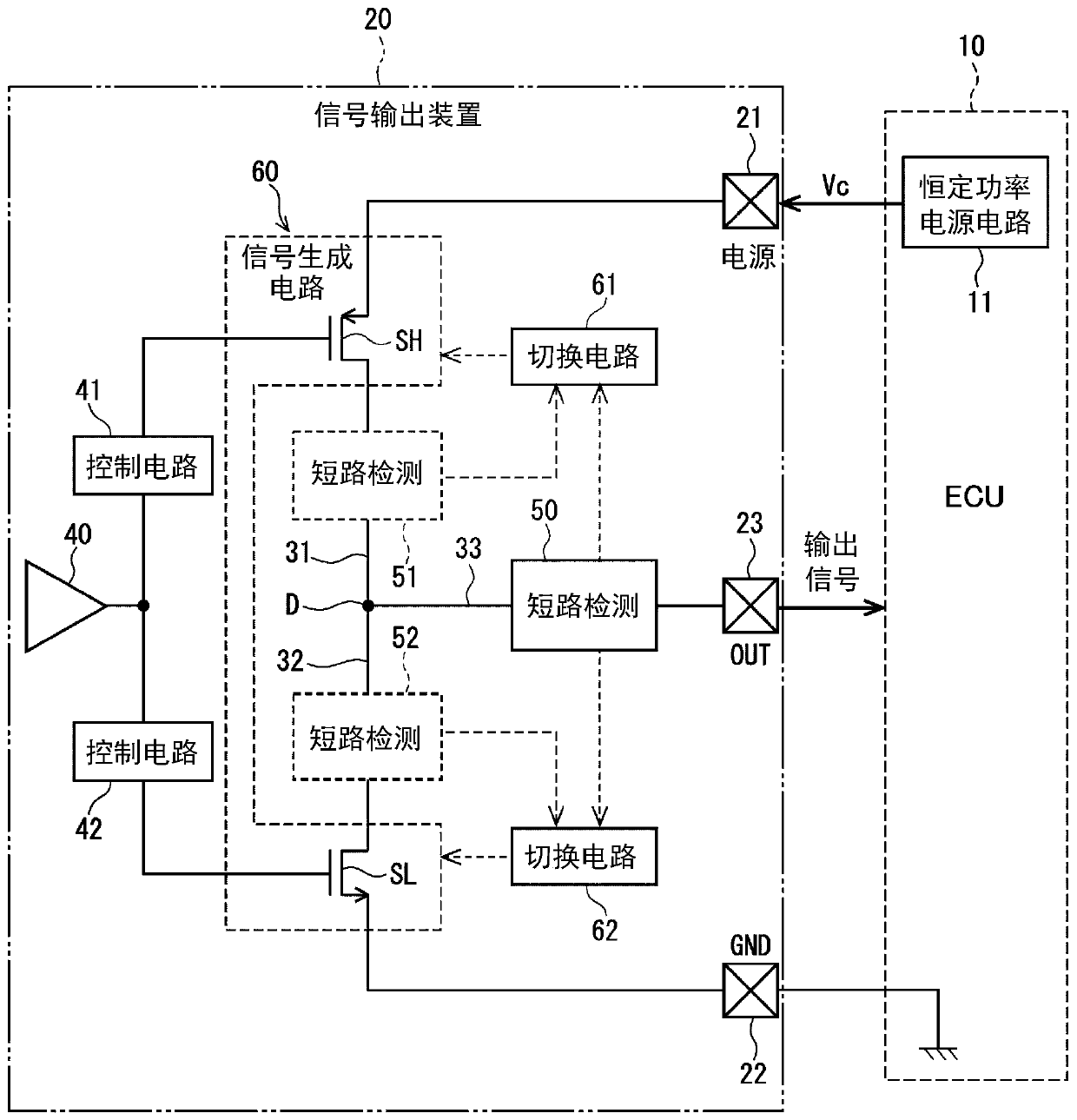
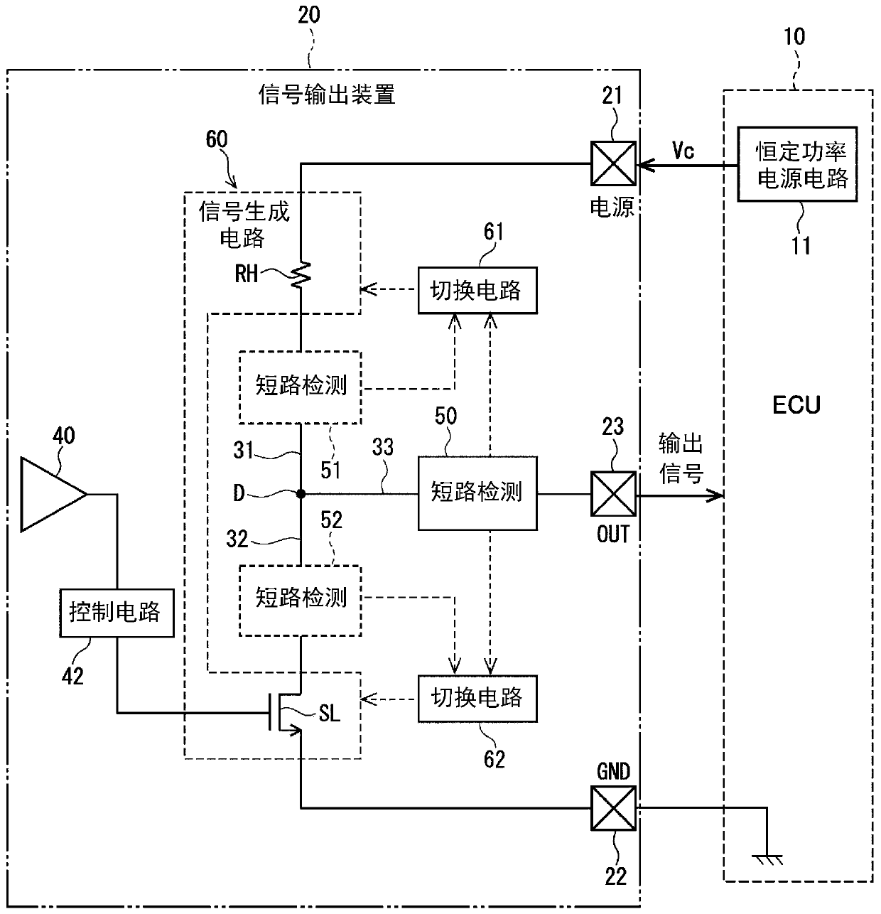
Signal output device

A signal output and signal generation technology, applied in signal transmission systems, transportation and packaging, instruments, etc., can solve problems such as unable to restore output, unable to ensure system stability, etc., to achieve the effect of ensuring stability and preventing adverse effects

Active Publication Date: 2020-07-17
DENSO CORP
7 Cites 0 Cited by

AI-Extracted Technical Summary

Problems solved by technology

As a result, the output cannot be restored even in a short-term short-circuit to such an extent that th...

Method used

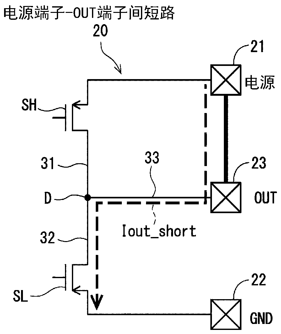
[0066] In the prior art shown in FIG. 19, the short-circuit detection threshold Iout_th is set larger than the normal current Iout_normal. That is, the relationship of the following formula (1) is satisfied. By setting the short-circuit detection threshold Iout_th to a value larger than the normal-time current Iout_normal, false detection of a short-circuit state during normal time is prevented.
[0073] Since the short-circuit c...

Abstract

In the present invention an output terminal (23) of a signal output device (20) is connected via a branch path (33) to a voltage division point (D) provided in the middle of main trunk paths (31, 32)connecting a power supply terminal (21) and a ground terminal (22), and transmits an output signal based on the voltage of the voltage division point (D) to the outside. A signal generation circuit (60) adjusts the voltage of the voltage division point (D) and generates the output signal. A short-circuit detection circuit (50) detects a short-circuit between the output terminal (23) and the otherterminals when a current flowing in the branch path (33) is greater than a prescribed short-circuit detection threshold value. When a short-circuit is detected by the short-circuit detection circuit (50) switching circuits (61, 62) switch the conduction capacity or the configuration of the signal generation circuit (60), thereby limiting the short-circuit current flowing in the branch path (33). The short-circuit current is set to a value equal to or greater than the short-circuit detection threshold value and less than an upper limit current value based on the supply capacity of a direct-current power supply.

Application Domain

Transmission systemsShort-circuit testing +2

Technology Topic

TelecommunicationsHemt circuits +5

Image

  • Signal output device
  • Signal output device
  • Signal output device

Examples

  • Experimental program(8)

Example

[0084] (First embodiment)
[0085] Picture 11 The signal generation circuit 601 of the first embodiment shown is provided with gate voltage regulators 71 and 72 that adjust the gate voltages of the switching element SH of the upper line 31 and the switching element SL of the lower line 32, respectively. When a short circuit is detected, the switching circuits 61 and 62 lower or raise the gate voltages of the switching elements SH and SL to switch the conduction capability of the signal generating circuit 601 to reduce the conduction current compared to normal times. In the Nmos transistor, the gate-source potential difference is reduced by reducing the gate voltage, and the on-current is reduced. In the Pmos transistor, the gate-source potential difference is reduced by increasing the gate voltage, and the on-current is reduced.

Example

[0086] (Second embodiment)
[0087] Picture 12 The signal generation circuit 602 of the second embodiment shown is provided with mirror elements MSH, MSL, and mirror elements MSH that connect the gates of the switching element SH of the upper line 31 and the switching element SL of the lower line 32 to each other. , MSL connection current regulator 71, 72. When a short circuit is detected, the switching circuits 61 and 62 reduce the current amount of the current source that is the reference of the switching elements SH, SL, which is the reference, to reduce the current flow of the switching signal generating circuit 602, and reduce the conduction current. small.

Example

[0088] (Third Embodiment)
[0089] Figure 13 In the signal generating circuit 603 of the third embodiment shown, two switching elements SH1 and SH2 are connected in parallel to the upper line 31, and two switching elements SL1 and SL2 are connected in parallel to the lower line 32. The gate of the switching element SH2 is connected to the control circuit 41 via a relay Ry2, and the gate of the switching element SL2 is connected to the control circuit 42 via a relay Ry4. In normal times, the relays Ry2 and Ry4 are connected, and the switching elements SH1 and SH2 and the switching elements SL1 and SL2 are all turned on, and a large conduction current can be energized by being connected in parallel.
[0090] When a short circuit is detected, the switching circuits 61 and 62 cut off the relays Ry2 and Ry4, so that the switching elements SH2 and SL2 no longer conduct. Therefore, only one switching element SH1 is turned on in the upper route 31, and only one switching element SL1 is turned on in the lower route 32, and the current Iout_short is limited during a short circuit. In this way, the switching circuits 61 and 62 of the third embodiment switch the signal generating circuit 603 in a manner that reduces the number of switching elements that are turned on among the plurality of switching elements connected in parallel when a short circuit is detected compared to normal times. Structure.

PUM

no PUM

Description & Claims & Application Information

We can also present the details of the Description, Claims and Application information to help users get a comprehensive understanding of the technical details of the patent, such as background art, summary of invention, brief description of drawings, description of embodiments, and other original content. On the other hand, users can also determine the specific scope of protection of the technology through the list of claims; as well as understand the changes in the life cycle of the technology with the presentation of the patent timeline. Login to view more.

Similar technology patents

Device for detecting oxygen concentration

InactiveCN105403619Alow costavoid adverse effects
Owner:FOSHAN KEYHUB ELECTRONICS IND CO LTD

Temperature control device of centrifugal casting machine

Owner:WEIER AUTOMATION CO LTD TANGSHAN IRON & STEELGRP

User anti-harassment system and method based on intelligent network

ActiveCN105763753Aavoid adverse effects
Owner:CHINA UNITED NETWORK COMM GRP CO LTD

Classification and recommendation of technical efficacy words

  • avoid adverse effects
  • Guaranteed stability

Touch control display panel

ActiveCN106802747AReduce border areaavoid adverse effects
Owner:XIAMEN TIANMA MICRO ELECTRONICS

Full-size quick blade detection method and equipment

Owner:HEILONGJIANG UNIVERSITY OF SCIENCE AND TECHNOLOGY

A ccd-type colloidal gold immunochromatographic diagnostic test paper quantitative analysis system

InactiveCN102279263AGuaranteed stabilityAddressing Subjective Bias
Owner:杭州顿力医疗器械有限公司

General clamp for abrasive flow polishing of complicated hole surface

InactiveCN104551985AContinuous and stable flowGuaranteed stability
Owner:CHANGCHUN UNIV OF SCI & TECH
Why Eureka
Try Eureka