Photoelectric switch of threading machine

A photoelectric switch, threading machine technology, applied in electronic switches, thread trimmers, electrical components and other directions, can solve problems such as damage to the threading machine, and achieve the effect of low cost and simple technology

Inactive Publication Date: 2020-07-21
SHAOXING JIANHUA METAL LOGISTICS CO LTD
View PDF0 Cites 0 Cited by
  • Summary
  • Abstract
  • Description
  • Claims
  • Application Information

AI Technical Summary

Problems solved by technology

[0002] At present, there are abnormal operating procedures in the field of threading machines. The abnormal operating procedures are threaded connections. This process will damage the threading machine and is clearly prohibited by the manufacturer in the neighborhood. The prior art does not exist It is technically prohibited and completely depends on the user's self-control. The present invention is technically configured to prohibit abnormal operating procedures

Method used


Image

  • Photoelectric switch of threading machine
  • Photoelectric switch of threading machine
  • Photoelectric switch of threading machine

Examples


Embodiment 1

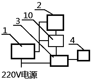
[0022] Example 1 see figure 1 A kind of photoelectric switch of thread threading machine, including strong and weak current transformer system 1, photoelectric switch 2, motor control device 3, motor 4, described motor 4 is connected with motor control device 3, accepts the control of motor control device 3, The motor control device 3 is connected to the photoelectric switch 2 to accept the control of the photoelectric switch 2, and the photoelectric switch 2 is connected to the strong and weak voltage transformation system 1 to receive the transformed safe voltage. In this embodiment, the photoelectric switch converts the change of light within the detection range into the change of electrical signal, and the process is a non-physical contact control process.

Embodiment 2

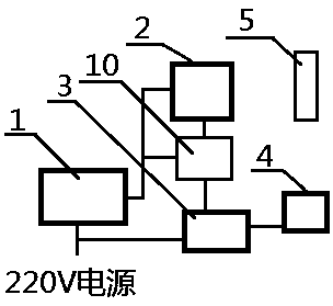
[0023] Example 2 see figure 2 , 3 With reference to Embodiment 1, in the application of Embodiment 1, when the photoelectric switch 2 detects the cutterhead 5, the photoelectric switch 2 controls the motor to shut down.

[0024] Further, when the photoelectric switch 2 detects the pipe wrench 6, the photoelectric switch 2 controls the motor to be in a shutdown state, so that the motor cannot be started.

[0025] Very good, the pipe wrench 6 detected by the photoelectric switch 2 is an abnormal operation process, which is explicitly prohibited by the manufacturer in the neighborhood to which it belongs. The existing technology does not prohibit it technically, and it is completely controlled by the user. The invention is technically set up, prohibiting abnormal operation procedures.

Embodiment 3

[0026] Embodiment 3 see Figure 4 , in combination with embodiments 1 and 2, a threading machine using a photoelectric switch, including a photoelectric switch of a threading machine and a threading machine itself, is characterized in that: the photoelectric switch of the threading machine The photoelectric switch is installed on the slide frame 11 of the threading machine 9, the motor control device on the photoelectric switch of the threading machine is connected with the local control device 10 of the threading machine, and the photoelectric switch 2 is used to detect the threading machine The position change of the cutterhead 5 on the machine when the cutter is retracted or the appearance of the pipe wrench 6.

[0027] Further, in the use of this embodiment, the pipe threading machine is threaded at the die head of the threading machine, the control device 10 of the threading machine is closed and the photoelectric switch starts the motor together, and the photoelectric sw...


PUM


Abstract

The invention provides a photoelectric switch of a threading machine. The photoelectric switch disclosed by the invention is simple in technique, low in cost and safe and reliable, and aims to solve the problem of technical control of an abnormal operation sequence, so that the using safety of the threading machine is improved, and the using reliability of the threading machine is greatly improved. The photoelectric switch is used for detecting abnormal operations by a photoelectric switch body, so that technical control on abnormal operation sequences is realized.

Description

technical field [0001] The invention relates to the field of threading machines, in particular to a photoelectric switch for threading machines. Background technique [0002] At present, there are abnormal operating procedures in the field of threading machines. The abnormal operating procedures are threaded connections. This process will damage the threading machine and is clearly prohibited by the manufacturer in the neighborhood. The prior art does not exist Prohibition technically depends entirely on the user's self-control. The present invention is technically configured to prohibit abnormal operating procedures. Contents of the invention [0003] Aiming at the above-mentioned deficiencies in the prior art, the present invention provides a photoelectric switch for a threading machine. The technology of the present invention is simple, low in cost, safe and reliable, solves the problem of technical control of abnormal operating procedures, and improves the safety of th...

Claims


Application Information

Patent Timeline
Patent Type & Authority Applications(China)
IPC IPC(8): B23G1/22B23G1/52H03K17/94
CPCB23G1/225B23G1/52H03K17/94
Inventor 平春华
Owner SHAOXING JIANHUA METAL LOGISTICS CO LTD
Why Eureka
Try Eureka