Pipe network pressure control circuit and system

A pipe network pressure and control circuit technology, applied in the field of control, can solve problems such as inability to waste energy consumption, difficult control of adjustment process and pressure accuracy, and labor-intensive, etc., to achieve the effect of low energy consumption management

Pending Publication Date: 2020-07-21
深圳拓安信物联股份有限公司
View PDF0 Cites 1 Cited by
  • Summary
  • Abstract
  • Description
  • Claims
  • Application Information

AI Technical Summary

Problems solved by technology

[0006] In view of this, the embodiment of the present invention provides a pipe network pressure control circuit, which aims to solve the traditional technical solutions that are labor-intensive, the adjustment process and pressure accuracy are difficult to control, and the downstream pipeline cannot be adjusted in real time according to the change of downstream pressure requirements. The pressure and the inability to centrally manage the power supply cause waste of energy

Method used


Image

  • Pipe network pressure control circuit and system
  • Pipe network pressure control circuit and system
  • Pipe network pressure control circuit and system

Examples


Embodiment Construction

[0036] In order to make the object, technical solution and advantages of the present invention clearer, the present invention will be further described in detail below in conjunction with the accompanying drawings and embodiments. It should be understood that the specific embodiments described here are only used to explain the present invention, not to limit the present invention.

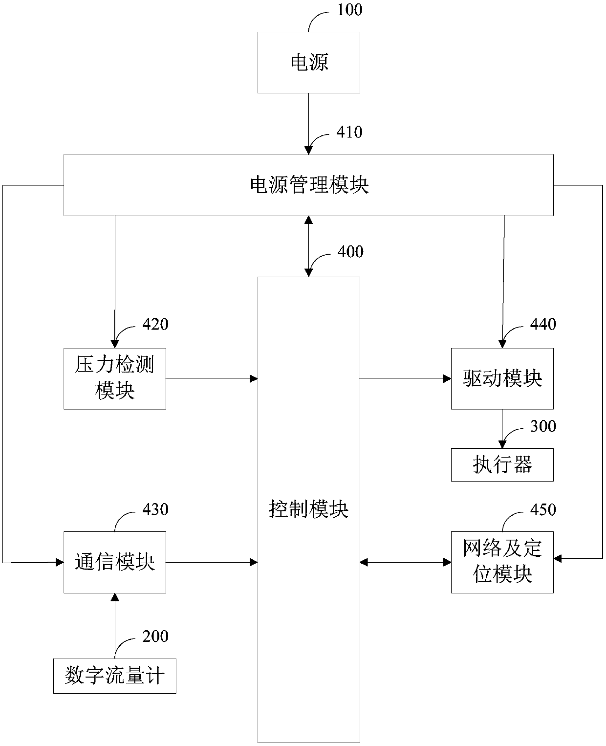
[0037] see figure 1 , the structural schematic diagram of the pipe network pressure control circuit provided by the first embodiment of the present invention, for the convenience of explanation, only shows the parts related to this embodiment, and the details are as follows:

[0038] In one embodiment, the pipe network pressure control circuit is connected to the power supply 100, the digital flowmeter 200, and the actuator 300. The power supply 100 can use a battery with a large storage capacity, such as a lithium battery, without an external commercial power supply 100, thereby facilitating insta...


PUM


Abstract

The invention relates to a pipe network pressure control circuit. A control module, a pressure detection module, a communication module and a driving module are additionally arranged to control the adjusting process and the pressure precision, and the control module controls the driving module according to a pipe network actual pressure value obtained from the pressure detection module or data ofa digital flow meter from the communication module, so that pipe network pressure changes are obtained in real time to adjust the pipe network pressure; and low-energy-consumption management is achieved by additionally arranging a power management module, downstream pressure changes are obtained in real time by additionally arranging a pressure detection module and the driving module to then adjust the pipe network pressure, the problem that due to the fact that the downstream pressure is too large, a pipeline is exploded or water does not exist due to too low pressure is avoided, and the problems that according to a traditional technical scheme, manpower is consumed, the adjusting process and the pressure precision are difficult to control, the pressure of the downstream pipeline cannot be adjusted in real time according to the changes of downstream pressure requirements, and energy consumption waste is caused due to the fact that a power source cannot be managed in a centralized modeare solved.

Description

technical field [0001] The invention belongs to the technical field of control, and in particular relates to a pipe network pressure control circuit and system. Background technique [0002] At present, the traditional pipe network pressure control management is mainly realized by adjusting the outlet pressure of the pressure reducing valves distributed in the water pipe network. There are two adjustment methods: [0003] One is manual adjustment, which meets the requirements of the water pipe network by manually adjusting the pressure reducing valve, but the manual adjustment method requires personnel to be on duty, and the adjustment process and pressure accuracy are difficult to control; [0004] The other is timing adjustment, which adjusts the pressure of the pipe network by preset fixed time and pressure, but the timing adjustment method cannot adjust the pressure of the downstream pipeline in real time as the downstream pressure demand changes, causing the downstream ...

Claims


Application Information

Patent Timeline
Patent Type & Authority Applications(China)
IPC IPC(8): F17D3/01
CPCF17D3/01
Inventor 邓立群袁培志李哲浩
Owner 深圳拓安信物联股份有限公司
Why Eureka
Try Eureka