
Flexible mechanism

A flexible and flexible part technology, applied in the field of flexible mechanisms, can solve the problems of increased difficulty, long setting time, and difficulty in quickly positioning at an accurate position, so as to improve production efficiency, reduce setting time, improve accuracy and response speed effect

Inactive Publication Date: 2020-07-21
HIWIN MIKROSYST
View PDF8 Cites 0 Cited by
  • Summary
  • Abstract
  • Description
  • Claims
  • Application Information

AI Technical Summary

Problems solved by technology

[0002] With the development of semiconductor nano-scale technology, equipment with high precision and high response speed has become the target of semiconductor equipment manufacturers' continuous technology research and development. Among them, the motion platform, which is widely used as a component unit of testing equipment, can provide high-speed motion. speed, but due to inertia, it is difficult for a moving object to stop at a precise position in a very short time, and generally speaking, the higher the moving speed of the object, the greater the degree of shaking before it stops completely. The longer the settling time, it is not easy to quickly locate the precise position
[0003] In the known technology, in order to eliminate the difficulty of setting due to the inertia of moving objects, it is revealed that a flexible mechanism is used to provide compensation for the motion error generated after the displacement, in order to reduce the time of setting and improve the accuracy. This is the existing technology. Sports items provide compensation for movement position errors, but in order to ensure the accuracy of the flexible mechanism itself, the known flexible mechanism makes its various components used to provide flexibility integrally formed, so that the known flexible The mechanism is more difficult to manufacture, and when maintenance is required due to elastic fatigue due to partial flexibility, the known flexible mechanism can only be dismantled and replaced as a whole. ineffective use of resources

Method used


Image

  • Flexible mechanism
  • Flexible mechanism
  • Flexible mechanism

Examples


Embodiment Construction

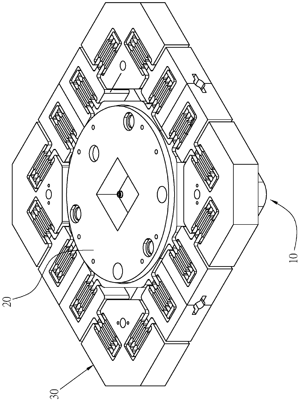
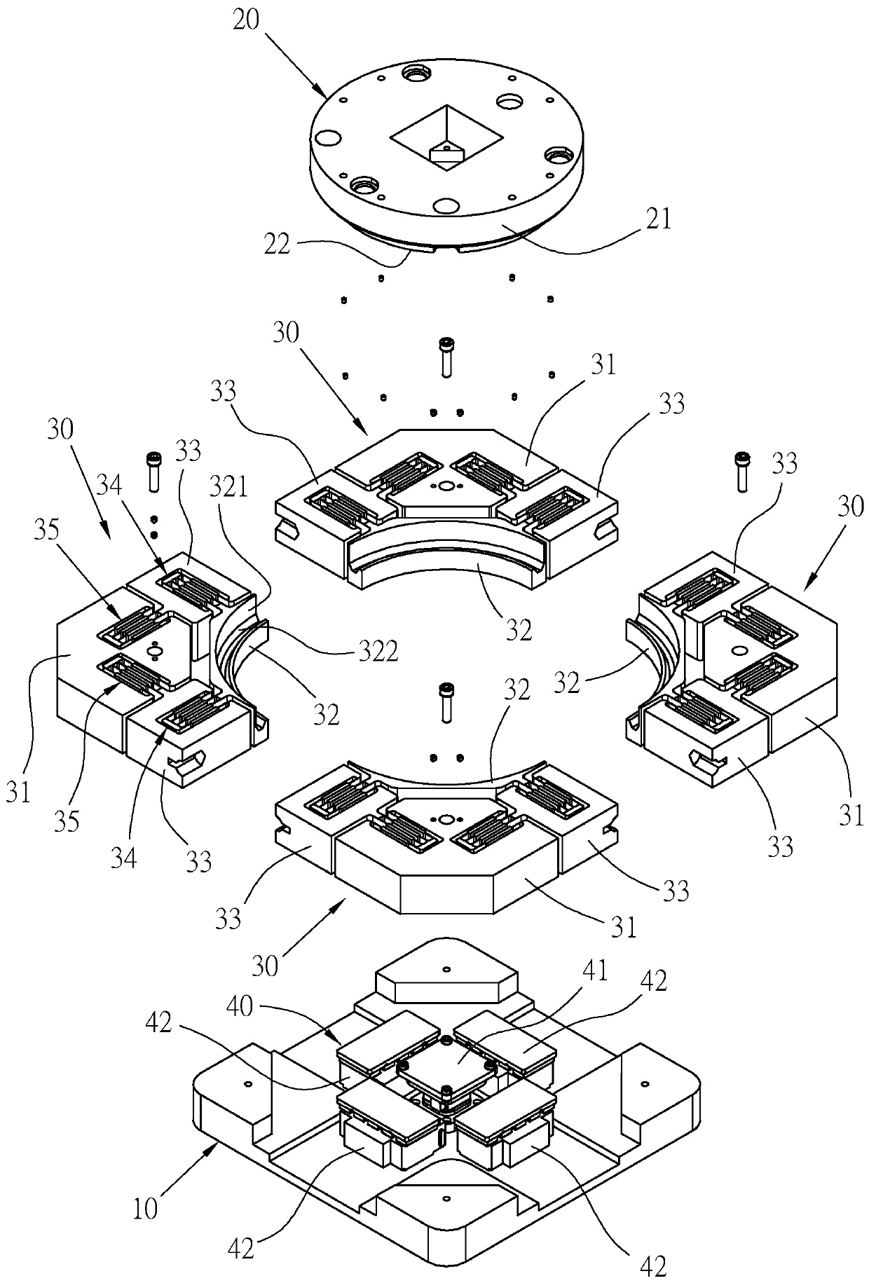
[0032] see Figure 1 to Figure 7 As shown, the flexible mechanism provided in the first embodiment of the present invention includes: a base 10; a platform 20, separated from the base 10; and a plurality of flexible units 30 bridged on Between the base 10 and the platform 20 . In this example, the number of flexible units 30 is four, and the design is modular, and can be combined with the base 10 and the platform 20 to form an integral component, and each flexible unit 30 can be replaced independently. When a certain flexible unit 30 is damaged due to fatigue, maintenance personnel only need to replace the flexible unit 30 without replacing the entire flexible mechanism, which greatly reduces the maintenance cost of the flexible mechanism and increases the convenience of maintenance and adjustment .

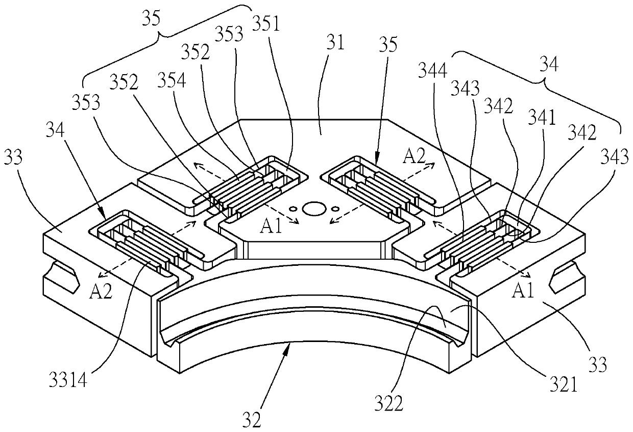
[0033] Each of the flexible units 30 has a first body portion 31 fixed on the base 10, a second body portion 32 connected to the platform 20 is separated from the first body po...


PUM


Abstract

The invention discloses a flexible mechanism. The flexible mechanism comprises a base, a platform separated from the base, and a plurality of flexible units which are bridged between the base and theplatform and are each provided with a first body part fixed on the base, a second body part connected with the platform and separated from the first body part, and a third body part respectively connected with the first body part and the second body part through a first flexible part and a second flexible part, wherein the first flexible part and the second flexible part have elasticity in different dimensions.

Description

technical field [0001] The present invention relates to motion platforms, and more particularly to a flexible mechanism. Background technique [0002] With the development of semiconductor nano-scale technology, equipment with high precision and high response speed has become the target of semiconductor equipment manufacturers' continuous technology research and development. Among them, the motion platform, which is widely used as a component unit of testing equipment, can provide high-speed motion. speed, but due to inertia, it is difficult for a moving object to stop at a precise position in a very short time, and generally speaking, the higher the moving speed of the object, the greater the degree of shaking before it stops completely. The longer the settling time, it is not easy to quickly locate the precise position. [0003] In the known technology, in order to eliminate the difficulty of setting due to the inertia of moving objects, it is revealed that a flexible mec...

Claims


Application Information

Patent Timeline
Patent Type & Authority Applications(China)
IPC IPC(8): G01D11/00
CPCG01D11/00
Inventor 李钧翔范智凯张宇荣
Owner HIWIN MIKROSYST
Learn More