Laser radar and camera synchronization method and device, equipment and storage medium

A lidar and camera technology, applied in the field of surveying and mapping, can solve the problem of not considering it, the lidar and the camera cannot be accurately synchronized, etc.

Active Publication Date: 2020-07-21
LEISHEN INTELLIGENT SYST CO LTD
View PDF5 Cites 6 Cited by
  • Summary
  • Abstract
  • Description
  • Claims
  • Application Information

AI Technical Summary

Problems solved by technology

[0004] However, this method only determines the relative error of the two sensors without conside

Method used


Image

  • Laser radar and camera synchronization method and device, equipment and storage medium
  • Laser radar and camera synchronization method and device, equipment and storage medium
  • Laser radar and camera synchronization method and device, equipment and storage medium

Examples


Embodiment 1

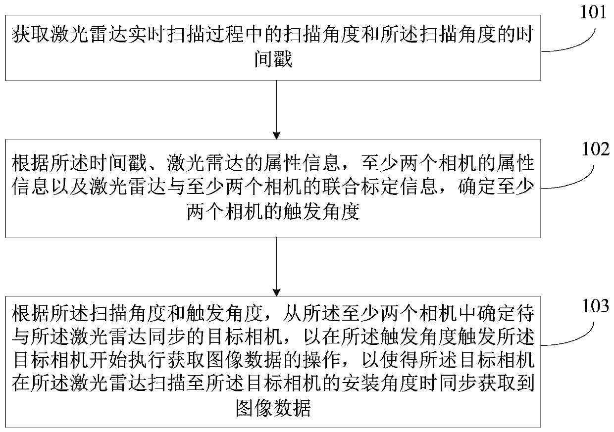
[0033] figure 1 It is a flow chart of the laser radar and camera synchronization method in Embodiment 1 of the present invention. This embodiment is applicable to solve the synchronization situation when the multi-line mechanical laser radar is used in combination with multiple cameras. The method can be performed by a laser radar and camera synchronization device, which can be implemented in software and / or hardware, and can be configured in a device. For example, the device can be a background server and other devices with communication and computing capabilities. Such as figure 1 As shown, the method specifically includes:

[0034] Step 101. Obtain the scanning angle and the time stamp of the scanning angle during the real-time scanning of the laser radar.

[0035] Among them, the laser radar is a radar system that emits laser beams to detect the position, speed and other characteristic quantities of the target. In the embodiment of the present invention, in order to anal...

Embodiment 2

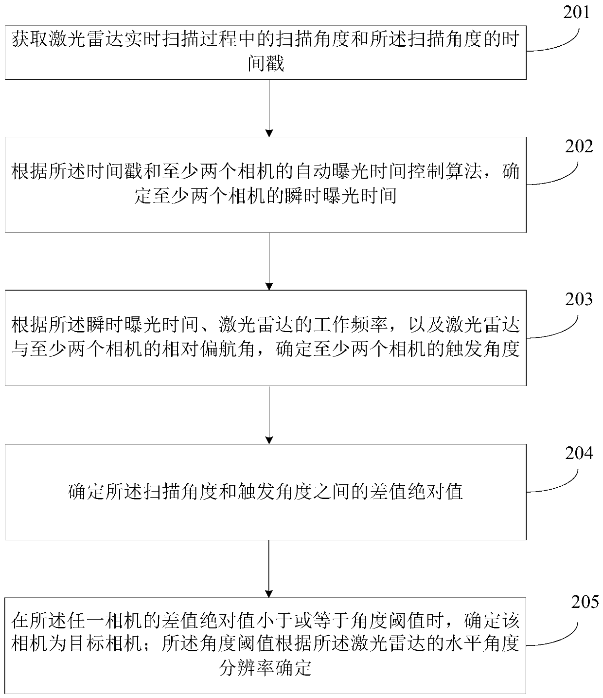
[0057] Fig. 2(a) is a flow chart of the method for synchronizing the lidar and the camera in the second embodiment of the present invention, and the second embodiment is further optimized on the basis of the first embodiment. As shown in Figure 2(a), the method includes:

[0058] Step 201. Obtain the scanning angle and the time stamp of the scanning angle during the real-time scanning of the laser radar.

[0059] Step 202: Determine the instantaneous exposure time of at least two cameras according to the time stamp and the automatic exposure time control algorithm of at least two cameras.

[0060] When triggering the camera to actually take pictures, due to the internal working principle of the camera, there will be a delay in the shooting of the camera. For example, the internal chip of the camera will have an automatic exposure time control algorithm, so that the actual shooting angle of the camera will be larger than the actual installation angle. error. Therefore, in ord...

Embodiment 3

[0080] image 3 It is a flow chart of the method for synchronizing the laser radar and the camera in the third embodiment of the present invention. This embodiment is applicable to solve the synchronization situation when the multi-line mechanical laser radar is used in combination with multiple cameras. The method can be performed by a laser radar and camera synchronization device, which can be implemented in software and / or hardware, and can be configured in a device. For example, the device can be a background server and other devices with communication and computing capabilities. Such as image 3 As shown, the method specifically includes:

[0081] Step 301. Obtain the scanning angle and the time stamp of the scanning angle during the real-time scanning of the lidar.

[0082] Step 302. Determine a target camera according to the scanning angle, joint calibration information of the lidar and at least two cameras.

[0083] According to the current scanning angle of the lid...


PUM


Abstract

The embodiment of the invention discloses a laser radar and camera synchronization method and device, equipment and a storage medium. The laser radar and camera synchronization method comprises the steps of obtaining a scanning angle and a timestamp of the scanning angle in a real-time scanning process of a laser radar; determining triggering angles of at least two cameras according to the timestamp, the attribute information of the laser radar, the attribute information of the at least two cameras and the joint calibration information of the laser radar and the at least two cameras; and determining a target camera to be synchronized with the laser radar from the at least two cameras according to the scanning angle and the triggering angle, so as to trigger the target camera at the triggering angle to start to execute the operation of acquiring image data, thereby enabling the target camera to synchronously acquire the image data when the laser radar scans to the installation angle ofthe target camera. The synchronization accuracy of the laser radar and the cameras is improved, and the fusion visual field of the laser radar and the multiple cameras is maximized.

Description

technical field [0001] Embodiments of the present invention relate to the technical field of surveying and mapping, and in particular, to a method, device, device, and storage medium for synchronizing a laser radar and a camera. Background technique [0002] In the field of surveying and mapping, lidar surveying and mapping, as a new type of three-dimensional measurement technology, has attracted more and more attention. Multi-line mechanical lidar is a measurement device that integrates laser scanning and positioning and attitude determination systems. It can highly accurately locate the spot of the laser beam on the object, and can accurately calculate the three-dimensional coordinates of each spot on the ground. However, lidar data lacks the original resolution of RGB images and efficient array structure. [0003] At present, in order to make up for the shortcomings of the single data structure of the point cloud obtained by the lidar, the lidar and the camera are used t...

Claims


Application Information

Patent Timeline
IPC IPC(8): G01S17/89G01C11/02
CPCG01C11/025G01S17/89
Inventor 胡小波丁航
Owner LEISHEN INTELLIGENT SYST CO LTD
Why Eureka
Try Eureka