Hospital disinfection device
A technology for disinfection devices and hospitals, applied in disinfection, water supply devices, sanitary equipment for toilets, etc., can solve the problem of inability to classify and disinfect medical devices, and achieve the effect of avoiding bump damage and improving disinfection efficiency.
- Summary
- Abstract
- Description
- Claims
- Application Information
AI Technical Summary
Problems solved by technology
Method used
Image

Examples
specific Embodiment approach 1
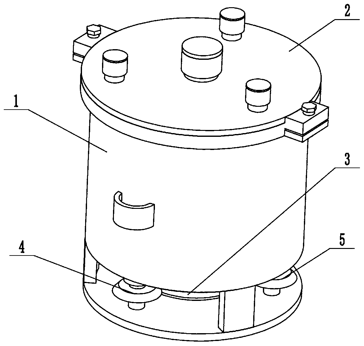
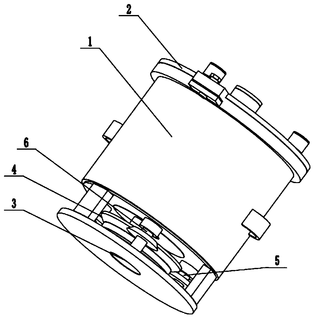
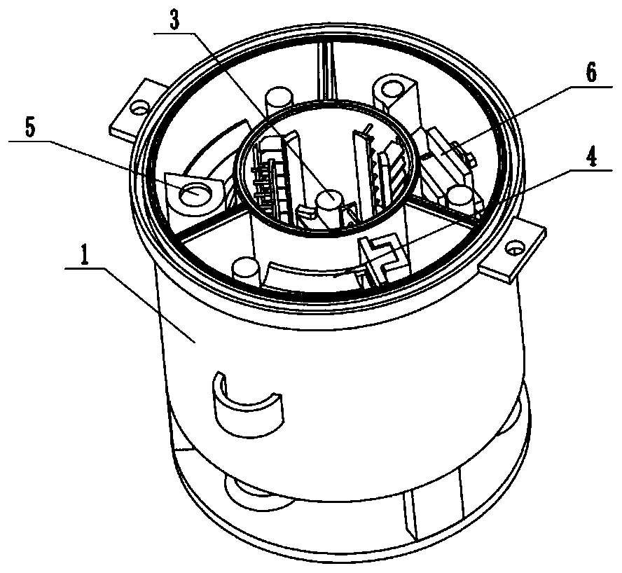
[0031] Such as Figure 1 to Figure 12 As shown, a hospital disinfection device includes a classification disinfection cylinder 1, a sealed upper end cover 2, a central disinfection driver 3, a tube disinfection driver 4, a mirror disinfection driver 5 and an irregular clamping disinfection driver 6. The sealed The upper end cover 2 is sealed and fitted on the upper end of the classification disinfection cylinder 1, and the sealed upper end cover 2 is fixedly connected to the upper ends of the central disinfection driver 3, the tube disinfection driver 4, the mirror disinfection driver 5 and the irregular clamping disinfection driver 6, and the center Disinfection driver 3, tube disinfection driver 4, mirror disinfection driver 5, and irregular clamping disinfection driver 6 are all sealed and rotated connected to the classification disinfection cylinder 1, and the central disinfection driver 3 is driven and meshed to connect the disinfection driver 4, mirror disinfection Drive...
specific Embodiment approach 2
[0033] Such as Figure 1 to Figure 12 As shown, this embodiment further explains Embodiment 1. The classification disinfection cylinder 1 includes a classification cylinder body 1-1, a locking sealing ring 1-2, a locking sealing groove 1-3, and a central partition cylinder 1-4. , three partition plates 1-5, separate sealing grooves 1-6, three longitudinal sliding grooves 1-7, three connecting blocks 1-8, motor fixing bottom plates 1-9 and threaded locking seats 1-10, locking The tight sealing ring 1-2 is fixedly connected to the upper side of the outer end of the classification cylinder 1-1, the locking sealing groove 1-3 is arranged on the locking sealing ring 1-2, and the central separation cylinder 1-4 is fixedly connected to the classification cylinder The lower end of the inner wall of 1-1, the three partition plates 1-5 are uniformly and fixedly connected in the central partition cylinder 1-4, and the inner ends of the three partition plates 1-5 are uniformly and fixedly...
specific Embodiment approach 3
[0035] Such as Figure 1 to Figure 12 As shown, this embodiment will further explain Embodiment 2. The sealed upper end cap 2 includes an upper end plate 2-1, a locking insert ring 2-2, four adding pipes 2-3, and four threaded sealing end caps. 2-4, two locking threaded seats 2-5, two locking bolts 2-6 and a separate sealing ring 2-7, the locking insert ring 2-2 is fixedly connected to the lower end of the upper end plate 2-1, and locked The insert ring 2-2 is fit in the locking sealing groove 1-3, the four adding pipes 2-3 are fixedly connected and communicated with the upper end of the upper end plate 2-1, and the four thread sealing end caps 2-4 are respectively sealed by threads Fittingly connected to the four adding pipes 2-3, the two locking threaded seats 2-5 are evenly fixed and connected to the outer wall of the upper end plate 2-1, and the locking bolts 2-6 are rotatably connected to the locking threaded seats 2-5 , the locking bolt 2-6 is connected in the threaded ...
PUM
 Abstract
Description
Claims
Application Information
 - Generate Ideas
- Intellectual Property
- Life Sciences
- Materials
- Tech Scout
- Unparalleled Data Quality
- Higher Quality Content
- 60% Fewer Hallucinations
Browse by: Latest US Patents, China's latest patents, Technical Efficacy Thesaurus, Application Domain, Technology Topic, Popular Technical Reports.
© 2025 PatSnap. All rights reserved.Legal|Privacy policy|Modern Slavery Act Transparency Statement|Sitemap|About US| Contact US: help@patsnap.com