
Movable exhaust pipe material frame system

An exhaust pipe and material rack technology, applied in metal processing, metal processing equipment, manufacturing tools, etc., can solve the problem of heavy workload of assembly workers, save manpower and time, avoid manpower lifting, and avoid musculoskeletal damage. Effect

Pending Publication Date: 2020-07-24
SHANGHAI OCEAN UNIV
View PDF2 Cites 3 Cited by
  • Summary
  • Abstract
  • Description
  • Claims
  • Application Information

AI Technical Summary

Problems solved by technology

Although these exhaust pipe material racks have improved the work efficiency of workers when taking materials, for the entire exhaust pipe assembly process, the workload of assembly workers is still huge, and there is still a large room for improvement in their work efficiency

Method used


Image

  • Movable exhaust pipe material frame system
  • Movable exhaust pipe material frame system
  • Movable exhaust pipe material frame system

Examples


Embodiment Construction

[0069] The specific implementation manners of the present invention will be further elaborated below in conjunction with the accompanying drawings.

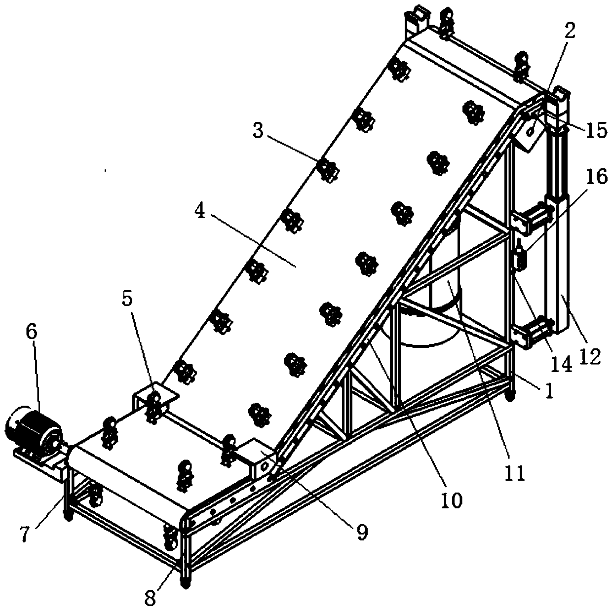
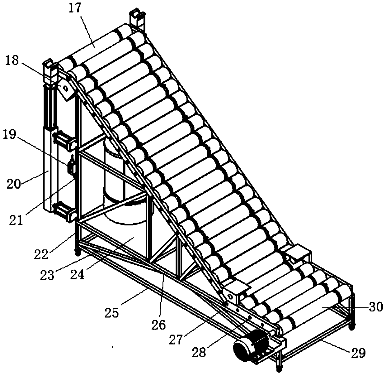
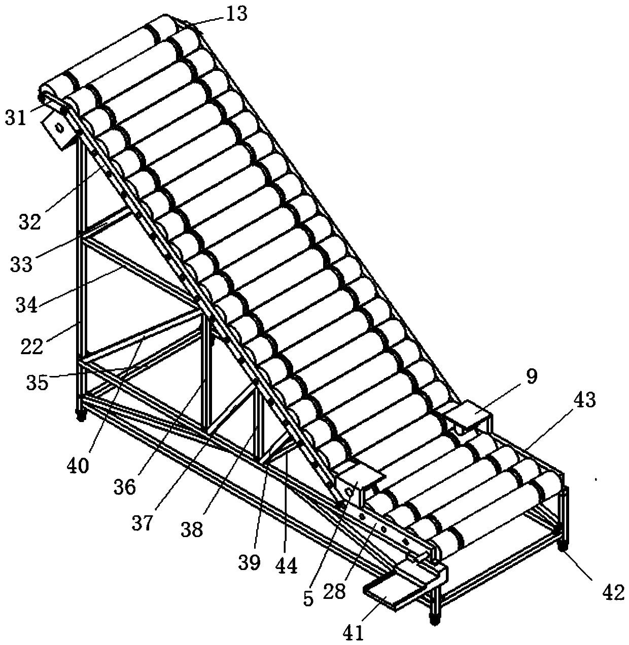
[0070] A mobile exhaust pipe material rack system, such as figure 1 As shown, it includes a conveyor belt 4 arranged in a Z shape as a whole, a central controller, a control switch I16, a control switch II 19 and two sets of pneumatic lifting devices (pneumatic lifting device I12 and pneumatic lifting device II 20), the conveyor belt 4 The middle section is an inclined slope with a slope of 30°, and the conveyor belt 4 is supported by a bracket;

[0071] stent such as figure 2 and 3 As shown, including the two side frames and the connectors connecting the two side frames (that is, a plurality of horizontal connecting beams connecting the two side frames, specifically the horizontal connecting beam I 29, the horizontal connecting beam II 35 and the horizontal connecting beam III 44), the two The side frames are identical and a...


PUM


Abstract

The invention discloses a movable exhaust pipe material frame system. The movable exhaust pipe material frame system comprises an inclined slope surface, wherein the inclined slope surface is supported by a bracket; universal wheels are arranged at the bottom of the bracket; a conveying belt is arranged on the inclined slope surface; a plurality of clamps used for fixing exhaust pipes are arrangedon the conveying belt; the conveying belt is driven by a reducing motor; a pneumatic lifting device for lifting the exhaust pipes is arranged on a higher side of the inclined slope surface; a row ofround rollers which are arranged closely are arranged in the conveying belt; one of the round rollers is a connecting shaft roller, and is connected with an output shaft of the reducing motor througha roller chain coupling; and the roller chain coupling is connected with the output shaft of the reducing motor and the connecting shaft roller through a key I and a key II respectively. The movable exhaust pipe material frame system disclosed by the invention is high in working efficiency, greatly reduces the workload of workers, is reasonable in design, relatively simple in structure, low in cost and great in use convenience, and has a great application prospect.

Description

technical field [0001] The invention belongs to the technical field of automobile assembly and relates to a movable exhaust pipe material rack system. Background technique [0002] In the current automobile assembly process, when installing the exhaust pipe, two operators are often required to go to a distant material rack to bend down to take the exhaust pipe, then lift the exhaust pipe to the bottom of the car chassis, and finally lift it up for tightening. Firmware installation. The material shelf where the exhaust pipe is placed is still a certain distance from the installation location, which is inconvenient to assemble and take materials by individuals; the material shelf has a small capacity, occupies a large area, and the number of logistics transportation increases the logistics cost, and can only store a single type of exhaust Pipes cannot meet the mixed-flow installation requirements of existing automobile exhaust pipes, and workers need to lift the exhaust pipes...

Claims


Application Information

Patent Timeline
Patent Type & Authority Applications(China)
IPC IPC(8): B23P19/00
CPCB23P19/001
Inventor 张丽珍廖伟阎竞博张展豪郭林菲李达林钊锐
Owner SHANGHAI OCEAN UNIV
Learn More