
Up and down hole combined cutting-well-free slot broaching method

A technology of cutting wells and pulling grooves, which is applied in earthwork drilling, underground mining, surface mining, etc., and can solve the problem of high accuracy requirements for forced pulling groove blast hole construction, difficult cutting groove single-stage blasting process, and medium-deep veins outside the veins. The problem of heavy hole construction workload and other problems, to achieve the effect of small blasting clamping effect, improve the working environment, and reduce the difficulty of construction

Active Publication Date: 2020-07-24
CHINA MINMETALS CHANGSHA MINING RES INST
View PDF7 Cites 7 Cited by
  • Summary
  • Abstract
  • Description
  • Claims
  • Application Information

AI Technical Summary

Problems solved by technology

However, the problem of this method is that the construction workload of the medium and deep holes outside the vein is large, the cutting groove single-stage blasting process is difficult, and additional rock drilling outside the vein is required.
However, this method of slotting has the disadvantages of high construction accuracy requirements for oblique symmetrical forced slotting blastholes, and large slotting with the top-over area as the free surface blasting.

Method used


Image

  • Up and down hole combined cutting-well-free slot broaching method
  • Up and down hole combined cutting-well-free slot broaching method
  • Up and down hole combined cutting-well-free slot broaching method

Examples


Embodiment 1

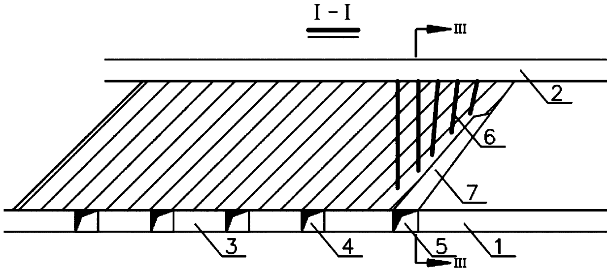
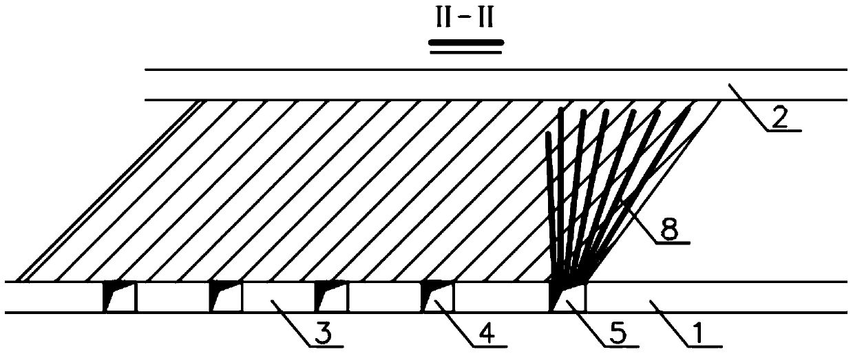
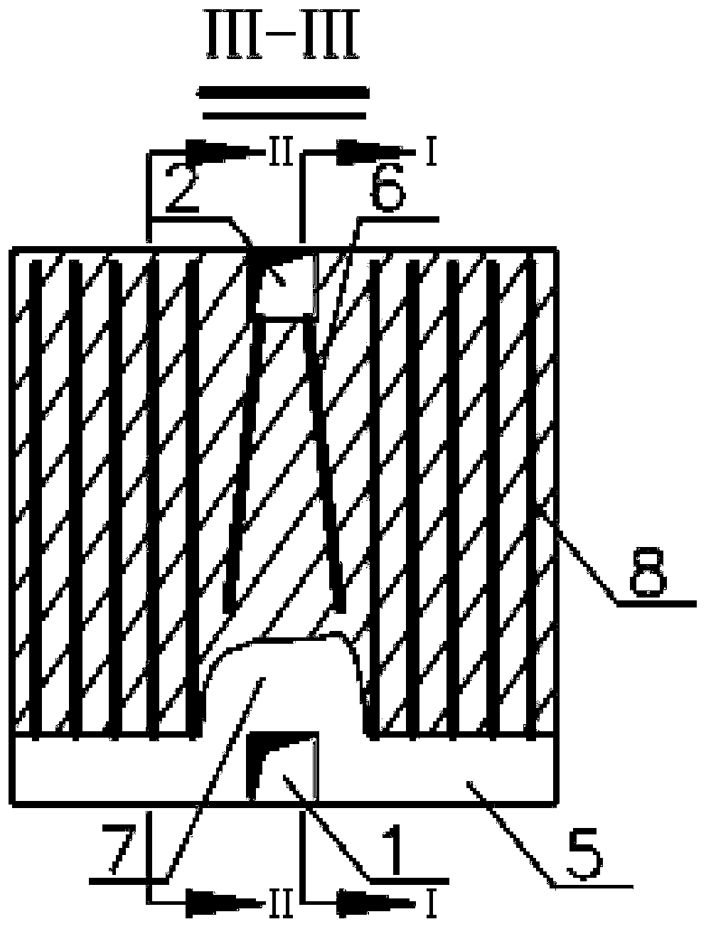
[0048] see Figure 1 to Figure 3 As shown, this embodiment provides a method of pulling grooves in combination with up and down holes without cutting wells:

[0049] Implementation background: In a gold mine, the average dip angle of the ore body is 38°, and the average thickness is 10m. The ore body occurs in the structural alteration zone and is strictly controlled by the structural fracture zone. Cut wells towards construction.

[0050] The specific construction steps of the slotting method are as follows:

[0051] S1, before pulling the cutting groove, first complete the layout and construction of the lower layer drilling roadway 1, the upper layer rock drilling roadway 2, the mine exit roadway 3, and the ore loading approach roadway 4, relying on the footwall of the ore body and vertically Under the construction of layer rock drilling roadway 1, layer cutting horizontal roadway 5, such as figure 1 and figure 2 shown; wherein, the section specification of the lower la...


PUM


Abstract

The invention provides an up and down hole combined cutting-well-free slot broaching method. The method comprises the steps that inclined down holes are constructed in corresponding positions of an upper layering rock chiseling roadway and a lower layering cutting transverse roadway through a down-the-hole drill, after the down holes are arranged and constructed, a lower ore roof falling zone andthe lower layering cutting transverse roadway serve as blasting free faces, and blasting is carried out to obtain a first blasting space; up slot broaching holes are mounted and constructed in the lower layering cutting transverse roadway, first blasting space formed through down hole blasting and the lower layering cutting transverse roadway serve as free faces, and segmented blasting is carriedout to form a complete cutting vertical slot. The down holes and up holes are combined to carry out slot broaching, the up holes take the blasting space formed by the down holes as the free faces, segmented blasting is carried out, the process is simple and reliable, and the method is safe and economic. The method is suitable for breaking ores, construction of a cutting well is not needed, high danger and cost of construction of the cutting well in fractured ore rock can be reduced, and giant application prospects can be achieved.

Description

technical field [0001] The invention relates to the technical field of mining, in particular to a method for pulling grooves in a vertically directed hole combined with a non-cutting well. Background technique [0002] When the stope is recovered, the cutting lane and the cutting patio are generally arranged at the end or the middle of the stope, and the cutting patio is used as the free surface to vertically pull the mining area to form a cutting groove. The formation of the cutting groove is the last process before mining in the mine, and it is also a very important process. Its purpose is to provide a free surface and enough compensation space for the stope blasting, and prepare for large-scale mine collapse. [0003] At present, the most commonly used grooving method is the vertical deep hole grooving method. Cutting cross-cuts are arranged in the direction perpendicular to the sectioned rock drilling roadway, and medium-deep holes or deep holes are drilled in the cuttin...

Claims


Application Information

Patent Timeline
Patent Type & Authority Applications(China)
IPC IPC(8): E21C41/22F42D3/04F42D1/00
CPCE21C41/22F42D1/00F42D3/04
Inventor 刘东锐李强李向东张为星盛佳王亚军张海云万兵周益龙朱青凌王玉丁李士超李晓辉
Owner CHINA MINMETALS CHANGSHA MINING RES INST
Learn More