Systems and methods for improving vehicle engine stability

An engine and stability technology, applied in engine control, engine components, machine/engine, etc., to solve problems such as increasing decompression time

Pending Publication Date: 2020-07-24
FORD GLOBAL TECH LLC
View PDF0 Cites 0 Cited by
  • Summary
  • Abstract
  • Description
  • Claims
  • Application Information

AI Technical Summary

Problems solved by technology

While such actions may avoid engine lag and/or stall, such actions may interrupt purging and/or fuel tank pressure control, which may result in increased depressu

Method used


Image

  • Systems and methods for improving vehicle engine stability
  • Systems and methods for improving vehicle engine stability
  • Systems and methods for improving vehicle engine stability

Examples


Example Embodiment

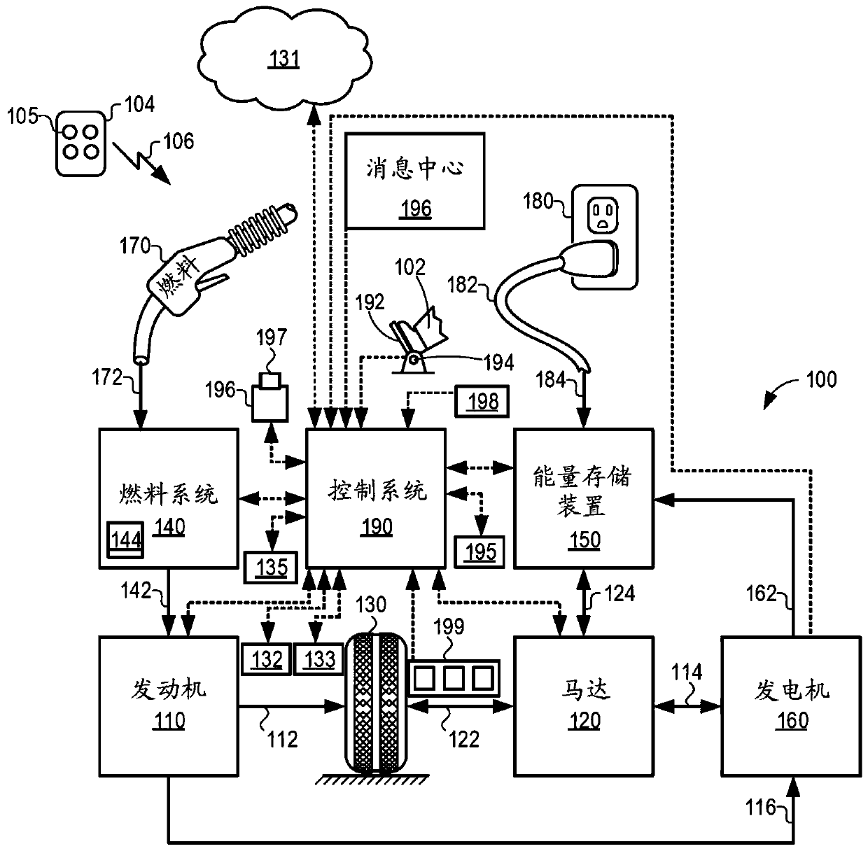
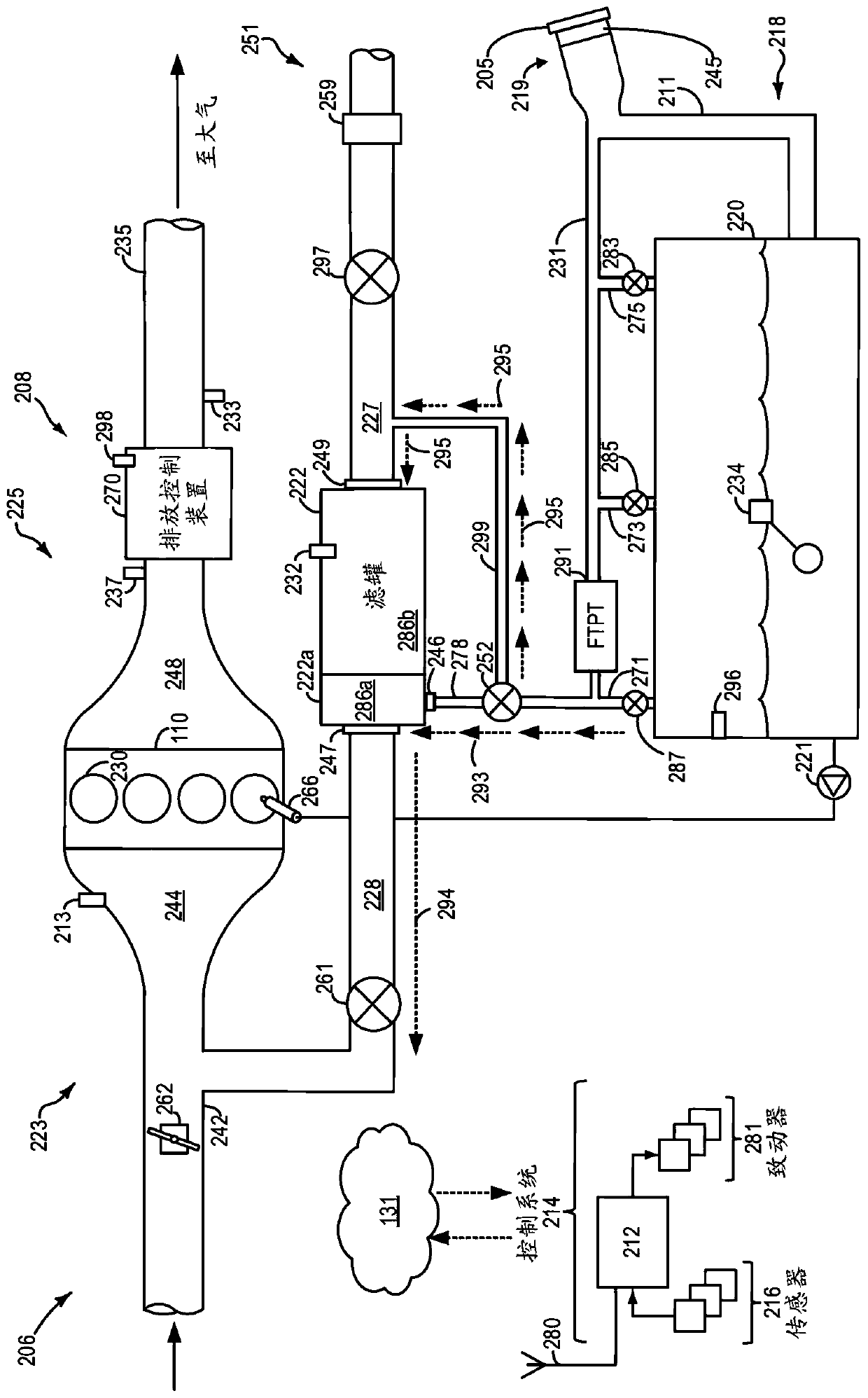
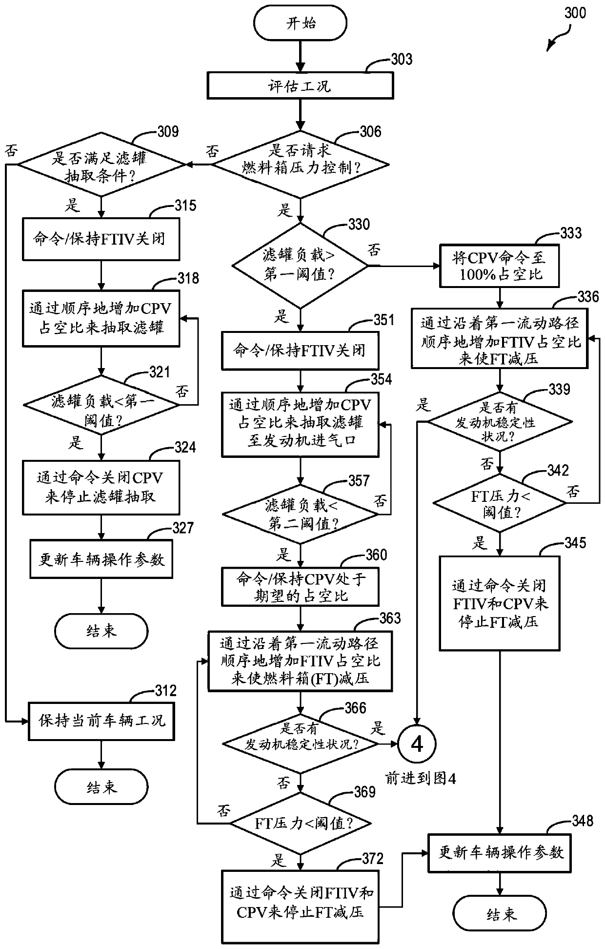
[0014] The following description relates to systems and methods for performing tank pressure control operations (also referred to herein as tank pressure control or TPC operations). In particular, such systems and methods relate to conducting TPC operations that can continue without having to abort. More specifically, for such TPC operation, fuel tank vapors may be directed along a first flow path that includes vapors being directed through a portion of the fuel vapor canister (eg, buffer zone) and then to the engine, provided that is a condition that does not indicate degraded engine stability. However, in response to such indications of degraded engine stability, the fuel vapors may then be redirected along a second flow path that includes the vapors being directed through the entire fuel vapor filter before being directed to the engine. Can. Such systems and methods are useful for hybrid electric vehicles with limited engine run time, such as figure 1 The depicted hybri...


PUM


Abstract

Systems and methods for improving vehicle engine stability. Methods and systems are provided for depressurizing a fuel tank of a vehicle by routing fuel tank vapors to an engine for combustion. In oneexample, a method may include reducing a pressure in the fuel tank by routing vapors from the fuel tank through a portion of a fuel vapor storage canister and, in response to an indication of a condition of degraded engine stability, re-routing the vapors from the fuel tank through an entirety of the fuel vapor storage canister. In this way, under conditions of degraded engine stability, a rate at which fuel tank vapors are directed to the engine may be reduced, which may thus mitigate the condition of degraded engine stability without aborting the operation to reduce the fuel tank pressure.

Description

technical field [0001] The present specification generally relates to methods and systems for controlling the amount of fuel vapors introduced into a vehicle engine from a fuel tank and a fuel vapor storage canister in response to an indication of a degraded engine stability condition. Background technique [0002] Vehicle emission control systems may be configured to store refueling vapors, and in some instances operating loss vapors and diurnal emissions, in a fuel vapor canister and then purge the stored vapors during subsequent engine operation. The stored vapors can be directed to the engine intake for combustion, further improving the vehicle's fuel economy. During a typical canister purge operation, the canister purge (CPV) coupled between the engine intake and the fuel vapor canister is opened or duty cycled, allowing intake manifold vacuum to be applied to the fuel vapor canister. Fresh air can be drawn in through the fuel vapor canister via the open canister vent...

Claims


Application Information

Patent Timeline
IPC IPC(8): F02D41/00F02M25/08
CPCF02D41/004F02M25/08F02M25/0836F02D29/02F02D41/0032F02D41/0035F02M25/0827F02M25/0854F02D2200/02
Inventor 艾德·杜道尔
Owner FORD GLOBAL TECH LLC
Why Eureka
Try Eureka