
Header Assemblies and Heat Exchangers

A header and heat exchanger technology, applied in the field of heat exchange, can solve the problems of concentrated liquid distribution, lower heat transfer performance of heat exchanger, uneven distribution of gas-liquid two-phase fluid, etc., and achieve uniform distribution of gas-liquid two-phase , Improve the effect of heat transfer performance

Active Publication Date: 2022-03-25
ZHEJIANG SANHUA INTELLIGENT CONTROLS CO LTD
View PDF8 Cites 0 Cited by
  • Summary
  • Abstract
  • Description
  • Claims
  • Application Information

AI Technical Summary

Problems solved by technology

This method is likely to cause uneven distribution of gas-liquid two-phase fluid in the header
Specifically, the collecting pipe usually has a first section close to the opening and a tail section far away from the opening. The fluid enters the collecting pipe through the opening, wherein the liquid tends to flow directly to the tail section due to the large inertia, causing the liquid to be concentrated and distributed in the The phenomenon of the tail section of the header
The gas-liquid two-phase distribution in the fluid is uneven, which reduces the heat transfer performance of the heat exchanger

Method used


Image

  • Header Assemblies and Heat Exchangers
  • Header Assemblies and Heat Exchangers
  • Header Assemblies and Heat Exchangers

Examples


Embodiment Construction

[0050] Exemplary embodiments will be described in detail herein, examples of which are illustrated in the accompanying drawings. Where the following description refers to the drawings, the same numerals in different drawings refer to the same or similar elements unless otherwise indicated. The implementations described in the illustrative examples below are not intended to represent all implementations consistent with the present invention. Rather, they are merely examples of apparatus and methods consistent with some aspects of the invention as recited in the appended claims.

[0051] The terminology used in the present invention is for the purpose of describing particular embodiments only and is not intended to limit the present invention. As used in this specification and the appended claims, the singular forms "a," "the," and "the" are intended to include the plural forms as well, unless the context clearly dictates otherwise. It will also be understood that the term "an...


PUM


Abstract

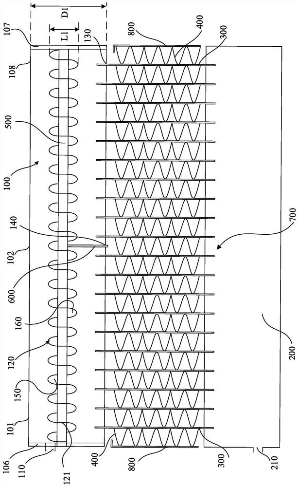
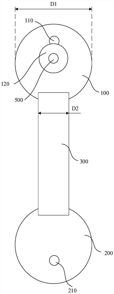
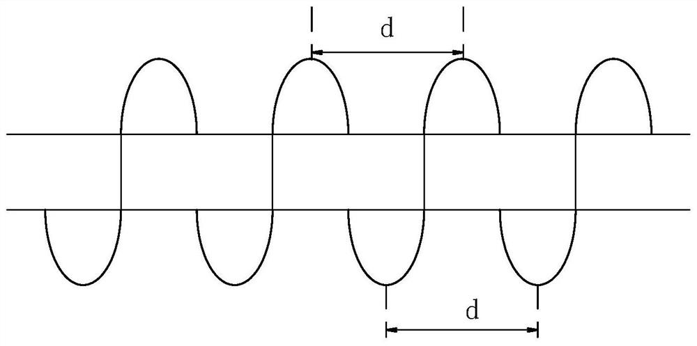
The invention discloses a header assembly and a heat exchanger. The manifold assembly includes a manifold and a swirl vane arranged in the manifold, the manifold has an opening for fluid to enter, and the swirl vane is arranged along the axial direction of the manifold extending helically and having a blocking surface extending radially of the header, the blocking surface facing the opening. In the above arrangement, a swirl sheet with a blocking surface is provided inside the header, so that the blocking surface of the swirl sheet can block part of the liquid from moving directly from one end of the header to the other end of the header due to inertia, The phenomenon of liquid accumulation at one end of the header is avoided, so that the gas-liquid two-phase distribution in the header is relatively uniform, and the heat exchange performance of the header assembly and the heat exchanger is improved.

Description

technical field [0001] The present application relates to the field of heat exchange, and in particular, to a header assembly and a heat exchanger. Background technique [0002] In the field of air conditioning, the application of microchannel heat exchangers is becoming more and more extensive. In the existing microchannel heat exchangers, the gas-liquid two-phase fluid directly enters the interior of the header through the opening opened in the header, and then Then enter the heat exchange tube. Such an approach is likely to cause uneven distribution of the gas-liquid two-phase fluid in the header. Specifically, the header usually has a first section close to the opening and a tail section away from the opening. The fluid enters the header through the opening, and the liquid easily flows directly to the tail section due to large inertia, causing the liquid to be concentrated and distributed in the header. Phenomenon of the tail section of the header. As a result, the ga...

Claims


Application Information

Patent Timeline
Patent Type & Authority Patents(China)
IPC IPC(8): F25B39/02F25B39/04F28F1/12
CPCF25B39/02F25B39/04F28F1/12
Inventor 不公告发明人
Owner ZHEJIANG SANHUA INTELLIGENT CONTROLS CO LTD
Learn More