Radar box body for safe auxiliary driving system

A technology of auxiliary driving and box body, which is applied in the direction of radio wave measurement system, measuring device, instrument, etc., can solve the problems of affecting the working performance of the radar, the temperature of the box body rises, and the service life of the box body and radar is reduced, so as to achieve enhanced heat dissipation And waterproof and anti-fog effect, guaranteed work performance, suitable for promotion and use

Pending Publication Date: 2020-07-24
扬州华强不锈钢有限公司
View PDF4 Cites 0 Cited by
  • Summary
  • Abstract
  • Description
  • Claims
  • Application Information

AI Technical Summary

Problems solved by technology

[0002] Vehicle-mounted radar is a radar used to implement functions such as obstacle measurement, collision prediction, and adaptive cruise control. It can effectively reduce driving difficulty, reduce driver burden, and reduce the incidence of accidents. It is especially widely used in special vehicles. , the current vehicle radar is installed in the box, the radar will generate heat when it is working, causing the temperature of the box to rise, and then it will cause the temperature of the box to drop
In this process, if the box body does not have cooling holes, it will cause the box body to expand and contract due to temperature changes. If this happens for a long time, the box body will be deformed due to this, and the waterproof and anti-fog effect of the currently used radar box is not ideal. , making the radar in the box susceptible to moisture, which not only affects the performance of the radar, but also reduces the service life of the box and the radar

Method used


Image

  • Radar box body for safe auxiliary driving system
  • Radar box body for safe auxiliary driving system
  • Radar box body for safe auxiliary driving system

Examples


Embodiment Construction

[0014] The following will clearly and completely describe the technical solutions in the embodiments of the present invention with reference to the accompanying drawings in the embodiments of the present invention. Obviously, the described embodiments are only some, not all, embodiments of the present invention. Based on the embodiments of the present invention, all other embodiments obtained by persons of ordinary skill in the art without making creative efforts belong to the protection scope of the present invention.

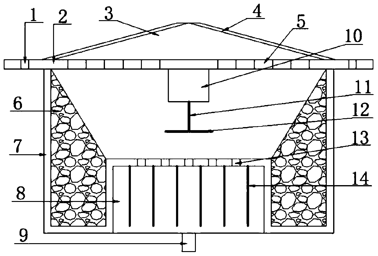
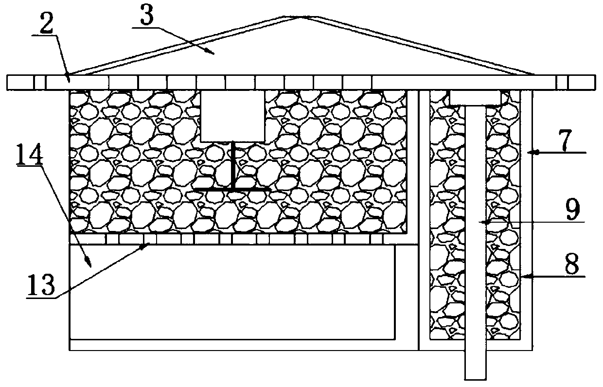
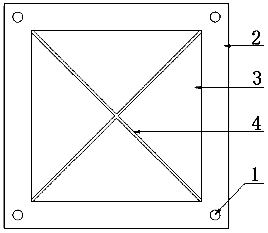
[0015] see figure 1 , the present invention provides a technical solution: a radar box for a safety assisted driving system, including a box cover 3, a box body 7, a mounting plate 2 is arranged on the top of the box body 7, and connecting holes are evenly opened on the left and right sides of the mounting plate 2 1. The installation plate 2 can be installed on the installation platform on the car through the connection hole 1. The middle position of the insta...


PUM


Abstract

The invention discloses a radar box body for a safe auxiliary driving system, and belongs to the technical field of vehicle auxiliary equipment. The radar box body comprises a box cover and a box body; a mounting plate is arranged at the top end of the box body; connecting holes are uniformly formed in the left side and the right side of the mounting plate; heat dissipation exhaust holes I are uniformly formed in the middle position of the mounting plate; a box cover is arranged at the top end of the mounting plate; water guide grooves are uniformly formed in the outer side of the box cover; apermanent magnet synchronous motor is fixedly arranged in the middle of the bottom end of the mounting plate; glass wool is adhered to the left and right sides of the inner cavity of the box body; heat dissipation exhaust holes II are uniformly formed in the middle of the bottom end of the inner cavity of the box body; and radiating fins are uniformly and fixedly arranged at the middle position of the bottom end of the box body. According to the radar box, the situations that the radar box body is deformed due to expansion and contraction caused by temperature change, and a radar in the box body is prone to being affected with damp due to the fact that water or fog exists outside the radar are reduced, working performance of the radar is guaranteed, and the service life of the box body and the service life of the radar are prolonged.

Description

technical field [0001] The invention relates to the technical field of vehicle auxiliary equipment, in particular to a radar box for a safety assisted driving system. Background technique [0002] Vehicle-mounted radar is a radar used to implement functions such as obstacle measurement, collision prediction, and adaptive cruise control. It can effectively reduce driving difficulty, reduce driver burden, and reduce the incidence of accidents. It is especially widely used in special vehicles. , At present, automotive radars are all installed in the box body. When the radar is working, it will generate heat, which will cause the temperature of the box body to rise, and then cause the temperature of the box body to drop. In this process, if the box body does not have cooling holes, it will cause the box body to expand and contract due to temperature changes. If this happens for a long time, the box body will be deformed due to this, and the waterproof and anti-fog effect of the ...

Claims


Application Information

Patent Timeline
Patent Type & Authority Applications(China)
IPC IPC(8): G01S7/02H05K5/06H05K7/20
CPCG01S7/02H05K7/20409H05K5/06G01S7/027
Inventor 吴朗勇
Owner 扬州华强不锈钢有限公司
Why Eureka
Try Eureka