Binocular camera calibration method and device, equipment and medium

A binocular camera and calibration method technology, applied in the field of robotics, can solve problems such as difficult to give positional relationship, installation error measurement, etc., to achieve the effect of solving deviation and error and improving accuracy

Pending Publication Date: 2020-07-24
GUANGDONG BOZHILIN ROBOT CO LTD
View PDF6 Cites 7 Cited by
  • Summary
  • Abstract
  • Description
  • Claims
  • Application Information

AI Technical Summary

Problems solved by technology

However, due to factors such as installation errors and measurement

Method used


Image

  • Binocular camera calibration method and device, equipment and medium
  • Binocular camera calibration method and device, equipment and medium
  • Binocular camera calibration method and device, equipment and medium

Examples


Embodiment 1

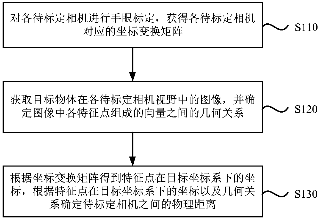
[0033] Figure 1a It is a flow chart of a binocular camera calibration method provided by Embodiment 1 of the present invention. This embodiment is applicable to the situation of calibrating binocular cameras or multi-eye cameras. The method can be performed by a binocular camera calibration device, which can be implemented in software and / or hardware, for example, the binocular camera calibration device can be configured in a computer device. Such as Figure 1a As shown, the method includes:

[0034] S110. Perform hand-eye calibration on each camera to be calibrated, and obtain a coordinate transformation matrix corresponding to each camera to be calibrated.

[0035] In this embodiment, the physical distance between the cameras to be calibrated is determined by the moving distance of the robotic arm. The movement distance of the robotic arm can be further determined by the offset of the robotic arm when acquiring the image of the target object in the field of view of each c...

Embodiment 2

[0069] Figure 2a It is a flow chart of a binocular camera calibration method provided by Embodiment 2 of the present invention. This embodiment is further optimized on the basis of the foregoing embodiments. Such as Figure 2a As shown, the method includes:

[0070] S210. Perform hand-eye calibration on each camera to be calibrated to obtain a coordinate transformation matrix corresponding to each camera to be calibrated, wherein the camera to be calibrated includes a first camera and a second camera.

[0071] S220. Acquire a first image of the target object in the field of view of the first camera, and a second image of the target object in the field of view of the second camera.

[0072] In this embodiment, the target object can be a checkerboard calibration object, and the checkerboard calibration object is placed at the center of the first camera and the second camera, and the mechanical arm is moved to obtain the positions of the checkerboard calibration object in the...

Embodiment 3

[0093] Figure 3a It is a flow chart of a binocular camera calibration method provided by Embodiment 3 of the present invention. This embodiment provides a preferred embodiment on the basis of the foregoing embodiments. Such as Figure 3a As shown, the method includes:

[0094] S310, setting the binocular camera, and adjusting the position of the mechanical arm.

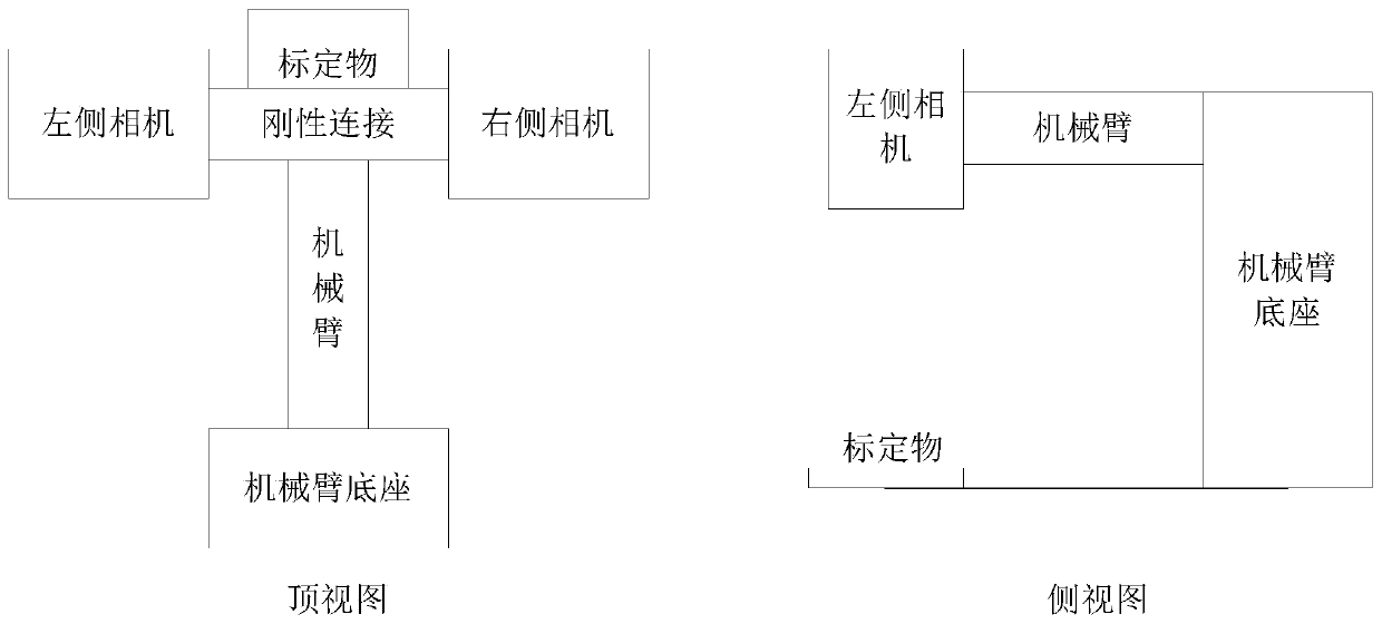
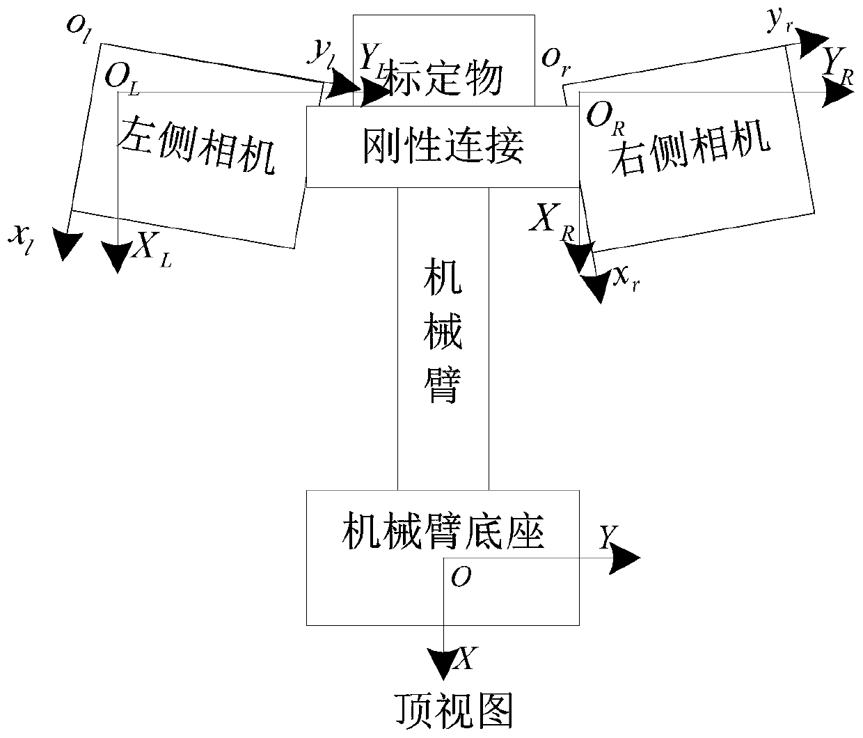
[0095] Install the two cameras on the bracket driven by the robotic arm, the cameras are rigidly connected, and the relative positions will not change. When installing, you only need to ensure that the camera is in the same direction, and there is no need to ensure that it is completely parallel. The bracket can be translated in the XY direction under the drive of the mechanical arm, and the camera will not rotate during the translation process. Among them, the position of the calibration object should be placed properly. When the left camera moves over the calibration object, the calibration object can complet...


PUM


Abstract

The embodiment of the invention discloses a binocular camera calibration method and device, equipment and a medium. The method comprises the steps: carrying out the hand-eye calibration of all to-be-calibrated cameras, and obtaining a coordinate transformation matrix corresponding to each to-be-calibrated camera; acquiring an image of the target object in the visual field of each to-be-calibratedcamera, and determining a geometrical relationship between vectors formed by the feature points in the image; and obtaining coordinates of the feature points in the target coordinate system accordingto the coordinate transformation matrix, and determining a physical distance between the to-be-calibrated cameras according to the coordinates of the feature points in the target coordinate system andthe geometrical relationship. According to the binocular camera calibration method provided by the embodiment of the invention, the coordinates of the feature points under the target coordinate system are obtained according to the coordinate transformation matrix corresponding to each to-be-calibrated camera; and the physical distance between the cameras to be calibrated is obtained by combiningthe geometrical relationship between the vectors formed by the feature points, so that the deviation and error caused by manual installation and measurement are solved, and the calibration accuracy ofthe binocular camera is improved.

Description

technical field [0001] The embodiments of the present invention relate to the field of robot technology, and in particular to a binocular camera calibration method, device, equipment and medium. Background technique [0002] With the continuous development of industrial automation and intelligence, the application of camera and image technology in the field of robotics is also improving. The combination of the robotic arm and the camera also allows the robot's "hand" and "eye" to complete tasks more efficiently and with high quality. At present, many robots will install binocular or multi-eye cameras, and the physical position relationship between the cameras of binocular cameras or multi-eye cameras is mostly given by measurement during installation. However, due to factors such as installation errors and measurement errors, it is difficult to give an accurate positional relationship. It can be seen that how to accurately calibrate the binocular camera is an unresolved te...

Claims


Application Information

Patent Timeline
IPC IPC(8): G06T7/80
CPCG06T7/85
Inventor 吴贵龙刘玉平丁智辉蒋涛江黄伟
Owner GUANGDONG BOZHILIN ROBOT CO LTD
Why Eureka
Try Eureka