Supercharge Your Innovation With Domain-Expert AI Agents!

Medical respiratory department indoor disinfection device

A technology for disinfection devices and departments, applied in the medical field, can solve the problems of inconvenient cleaning and replacement of parts, inconvenient device installation and disassembly, etc., and achieve the effects of easy installation and replacement, easy installation and disassembly, and convenient use.

Inactive Publication Date: 2020-07-28
闫志伟
View PDF10 Cites 0 Cited by
  • Summary
  • Abstract
  • Description
  • Claims
  • Application Information

AI Technical Summary

Problems solved by technology

For this reason, an object of the present invention is to provide a kind of disinfection device in the medical respiratory department, which can solve the problem of inconvenient installation and disassembly of the device, and inconvenient cleaning and replacement of the cleaning part after the device is sterilized.

Method used


Image

  • Medical respiratory department indoor disinfection device
  • Medical respiratory department indoor disinfection device
  • Medical respiratory department indoor disinfection device

Examples


Embodiment 1

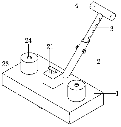
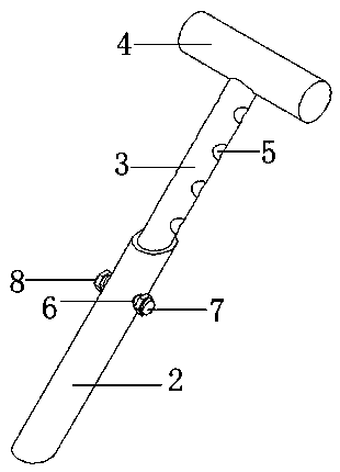
[0029] Such as figure 1 with figure 2 As shown, a medical respiratory department indoor disinfection device includes a main board 1, a sleeve 2 is fixed on the top edge of the main board 1, the center of the bottom end of the sleeve 2 is located on the center line of the top of the main board 1, and the sleeve 2 is arranged obliquely on the top of the main board 1 and The angle of inclination is between forty-five degrees and sixty degrees. A movable rod 3 is sleeved inside the sleeve pipe 2. The length of the movable rod 3 is equal to the length of the sleeve pipe 2. The end of the movable rod 3 is fixed with a push rod 4. The surface wall of the rod 3 is evenly spaced with through screw holes 5, and the top edge of the side wall of the casing 2 is provided with a connecting screw hole 6 that matches the through screw hole 5, and the connecting screw hole 6 and the through screw hole 5 are internally threaded. Double-ended screw rod 7, the length of double-ended screw rod 7...

Embodiment 2

[0031] Embodiment two is a further improvement on embodiment one.

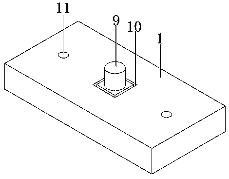
[0032] Such as image 3 with Figure 4As shown, a motor 9 is fixed at the center of the top of the mainboard 1, an installation ring groove 10 is provided at the center of the top of the mainboard 1, two groups of installation pipes 11 are symmetrically provided at the top of the mainboard 1, and a circular groove 12 is provided at the center of the bottom end of the mainboard 1, and the installation pipe 11 It is an L-shaped pipe and the end runs through the center of the side wall of the installation circular groove 12, the sum of the depth of the installation ring groove 10 and the depth of the installation circular groove 12 is less than the thickness of the main board 1, and the depth of the installation circular groove 12 is greater than half of the thickness of the main board 1, The installation circular groove 12 is communicated with the installation pipe 11, and the center of the top of the installat...

Embodiment 3

[0034] Embodiment three is a further improvement on embodiment two.

[0035] Such as Figure 5 with Image 6 As shown, the installation ring groove 10 is magnetically connected with the installation ring plate 20, the shape and size of the installation ring plate 20 is equal to the shape and size of the installation ring groove 10, the top of the installation ring plate 20 is fixed with a protective box 21, and the size of the inner space of the protective box 21 Greater than the size of the motor 9, the center of the top of the protective box 21 is fixed with a handle 22, the top of the handle 22 and the push rod 4 are provided with a rubber protection pad, the center of the top of the installation pipe 11 is fixed with a disinfectant tube 23, and the center of the top of the tube 23 is An opening 24 is provided, and a connecting pipe 25 is installed inside the installation pipe 11. The connecting pipe 25 communicates with the disinfectant liquid cylinder 23 and a solenoid v...


PUM


Abstract

The invention relates to the field of medical treatment, in particular to a medical respiratory department indoor disinfection device. A sleeve, a movable rod, penetrating screw holes, connecting screw holes and a double-thread screw rod are arranged, the movable rod and the sleeve are movably inserted and matched, so that the movable rod is convenient to install, meanwhile, the proper penetratingscrew holes can be selected to be aligned with the connecting screw holes, and the double-thread screw rod is used for installation and fixation, the extending length of the movable rod can be adjusted according to the height of an operator, and use is convenient; an elastic lantern ring, cleaning cloth, communicating pipes, disinfectant cylinders and water spraying plates are arranged, a disinfectant in the disinfectant cylinders can be sprayed out through the water spraying plates by means of the communicating pipes and then conveyed to the cleaning cloth through water leaking holes, underthe cooperation of a motor and an electric push rod, the indoor ground with sputum in the respiratory department is cleaned and disinfected in a rotating mode, and meanwhile the elastic lantern ring is arranged in a sleeving mode, so that installation and replacement are convenient.

Description

technical field [0001] The invention relates to the medical field, in particular to a disinfection device for a medical respiratory department. Background technique [0002] In the current disinfection equipment technology used in the respiratory department, most of the disinfection equipment basically uses a hand-held disinfection tube to disinfect the bacteria inside the ward when disinfecting the respiratory ward. But clinical practice has learned that a large number of infectious bacteria are contained in the saliva and thick sputum spit out by respiratory patients. At present, when nursing patients with respiratory diseases in the respiratory department of the hospital, the spittoon is generally used to collect the patient's sputum. Hidden dangers, the traditional mop cleaning cannot be used for disinfection and sterilization, and the sputum spit by patients cannot be scrubbed and disinfected in time, and it may infect medical staff and nursing family members. When sc...

Claims


Application Information

Patent Timeline
Patent Type & Authority Applications(China)
IPC IPC(8): A47L11/283A47L11/40A61L2/18A61L2/26
CPCA47L11/283A47L11/4075A47L11/408A61L2/18A61L2/26A61L2202/15
Inventor 闫志伟
Owner 闫志伟
Features
  • R&D
  • Intellectual Property
  • Life Sciences
  • Materials
  • Tech Scout
  • Unparalleled Data Quality
  • Higher Quality Content
  • 60% Fewer Hallucinations
Learn More