Crude oil storage tank automatic drainage oil retention system and drainage oil retention method thereof

A crude oil storage tank, automatic drainage technology, used in packaging, large containers, transportation and packaging, etc., to achieve the effect of adjustable displacement

Pending Publication Date: 2020-07-28
BC P INC CHINA NAT PETROLEUM CORP +1
View PDF0 Cites 1 Cited by
  • Summary
  • Abstract
  • Description
  • Claims
  • Application Information

AI Technical Summary

Problems solved by technology

[0003] In view of this, the purpose of the present invention is to provide a crude oil storage tank automatic drainage oil cut-off system and its drainage oil cut-off method, for overcoming the above-mentioned problems or at least partly solving or alleviating the above-mentioned problems

Method used


Image

  • Crude oil storage tank automatic drainage oil retention system and drainage oil retention method thereof

Examples


Embodiment 1

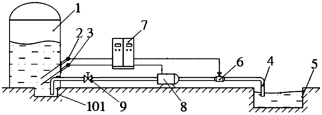
[0026] refer to figure 1 , the embodiment of the present invention proposes a kind of crude oil storage tank automatic drainage and cut-off system, comprising: crude oil storage tank 1, drainage pipeline 4 and CQ type oil-water on-line control device 7; The detector 2 is provided with a lower oil-water layer detector 3 at the bottom; the inlet of the drainage pipeline 4 leads to the bottom of the crude oil storage tank 1, the outlet of the drainage pipeline 4 leads to the sewage pool 5, and the drainage pipeline 4 is provided with a solenoid valve 6; The CQ type oil-water online monitoring device 7 is provided with a GJ type high-precision analog-to-digital converter, a CC type memory, an FX type analysis processor, a KZ type control circuit and a TX type communication circuit, and the CQ type oil / water online monitoring device 7 communicates with the RTU type remote control terminal signal connection, the signal input end of CQ type oil-water online monitoring device 7 is ele...

Embodiment 2

[0031] refer to figure 1 , on the basis of Embodiment 1, it also includes a drainage pump 8, and the drainage pump 8 is electrically connected to the signal output end of the CQ type oil-water online monitoring device 7.

[0032] The drainage pump 8 can pump the water in the crude oil storage tank 1 into the sewage tank 5 through the drainage pipeline 4, so as to increase the drainage speed.

Embodiment 3

[0034] refer to figure 1 , On the basis of Embodiment 1, the CQ type oil-water online monitoring device 7 is also provided with manual control buttons, which can control the solenoid valve 6 and the drain pump 8 respectively.

[0035] When the signal connection between the CQ-type oil-water online monitoring device 7 and the RTU-type remote control terminal is interrupted, the on-site staff can directly control the opening and closing of the solenoid valve 6 and the drainage pump 8 through the manual control buttons on the CQ-type oil-water online monitoring device 7 .


PUM


Abstract

The invention provides a crude oil storage tank automatic drainage oil retention system which comprises a crude oil storage tank, a drainage pipeline and an oil-water online control device. An upper oil-water layering detector is arranged at the upper portion inside the crude oil storage tank. A lower oil-water layering detector is arranged at the lower portion inside the crude oil storage tank. An inlet of the drainage pipeline is led into the bottom of the crude oil storage tank. An outlet of the drainage pipeline is led into a sewage pond, and an electromagnetic valve is arranged on the drainage pipeline. The oil-water online monitoring device is in signal connection with a remote control terminal through a communication circuit. The signal input end of the oil-water online monitoring device is electrically connected with the upper oil-water layering detector and the lower oil-water layering detector separately. The signal output end of the oil-water online monitoring device is electrically connected with the electromagnetic valve. The invention further provides a crude oil storage tank automatic drainage oil retention method implemented by adopting the crude oil storage tank automatic drainage oil retention system.

Description

technical field [0001] The invention belongs to the technical field of crude oil monitoring, and in particular relates to an automatic drainage and oil interception system for a crude oil storage tank and a drainage and oil interception method thereof. Background technique [0002] In the process of oil production and processing, due to the influence of many factors, it has always been a difficult problem to drain oil from crude oil storage tanks. For a long time, crude oil storage tank drainage and oil interception have been carried out by manual liquid level gauge and manual sampling, which has many disadvantages, such as large error, heavy workload, high cost, unsatisfactory sewage discharge, and low degree of automation of manual sewage discharge. , Under abnormal circumstances, the oil product will flow out from the drainage pipe, causing serious consequences of the accident. Contents of the invention [0003] In view of this, the object of the present invention is t...

Claims


Application Information

Patent Timeline
Patent Type & Authority Applications(China)
IPC IPC(8): B65D88/54B65D90/48
CPCB65D88/546B65D90/48
Inventor 高宝元
Owner BC P INC CHINA NAT PETROLEUM CORP
Why Eureka
Try Eureka