Abut-joint device

A docking device and docking interface technology, applied in the direction of transportation and packaging, conveyor objects, etc., can solve the problems of low test pass rate and test efficiency, vibration and offset of the docking female end, and affect the service life of the docking device, etc., to improve Test pass rate and test efficiency, solve the effect of poor docking stability, and improve docking accuracy

Inactive Publication Date: 2020-07-28
HISENSE VISUAL TECH CO LTD
View PDF6 Cites 1 Cited by
  • Summary
  • Abstract
  • Description
  • Claims
  • Application Information

AI Technical Summary

Problems solved by technology

[0004] However, when the docked female end is moved to the corresponding position of the docked male end through the wire body pallet, in order to avoid restarting the board after the test is completed, the wire body pallet will usually continue to move the board, which makes the docked female end Vibration and offset are generated during the process, making it difficult to achieve precise docking with the docking male end, which will easily lead to poor contact between the test signal source and the TV, thereby affecting the stability of signal transmission, resulting in low test pass rate and test efficiency
In addition, the vibration and offset of the docking female end during the docking process will also cause friction with the docking male end, which will affect the service life of the docking device

Method used


Image

  • Abut-joint device
  • Abut-joint device
  • Abut-joint device

Examples


Embodiment Construction

[0026] In order to enable those skilled in the art to better understand the technical solutions in the present application, the technical solutions in the embodiments of the present application will be clearly and completely described below in conjunction with the drawings in the embodiments of the present application. Obviously, the described The embodiments are only some of the embodiments of the present application, not all of them. Based on the embodiments in this application, all other embodiments obtained by persons of ordinary skill in the art without creative efforts shall fall within the scope of protection of this application.

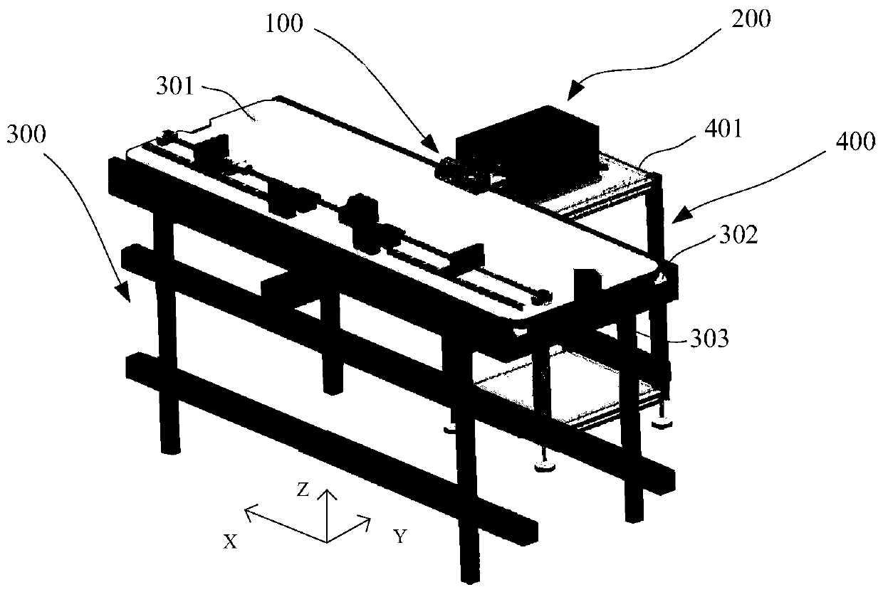
[0027] figure 1 A docking system architecture diagram provided for the embodiment of this application, such as figure 1 As shown, the docking system includes a docking female end 100, a docking male end 200, a docking female end transfer device 300, and a docking male end support device 400, wherein the docking female end 100 and the docking...


PUM


Abstract

The embodiment of the invention provides an abut-joint device. The abut-joint device comprises an abut-joint female end and an abut-joint male end, wherein the abut-joint female end comprises a femaleend panel, an abut-joint guide hole and a female end abut-joint connector are mounted, the abut-joint male end comprises a male end panel, a propelling mechanism and a buffer adjusting mechanism, thepropelling mechanism and the buffer adjusting mechanism are connected with the male end panel, an abut-joint guide part is mounted at the position, corresponding to the abut-joint guide hole, of themale end panel, a male end abut-joint connector is formed in the position, corresponding to the female end abut-joint connector, of the male end panel, the propelling mechanism is used for propellingthe male end panel to move in the direction perpendicular to the abut-joint female end, the buffer adjusting mechanism is used for adjusting the position of the male end panel so as to buffer the vibration of the female end panel, through the abut-joint guide part and the abut-joint guide hole, abut-joint rough positioning is achieved, through the propelling mechanism, abut-joint precise positioning is achieved, the abut-joint precision is improved, through the buffer adjusting mechanism, the abut-joint male end can carry out buffer and automatic guide on deviation and vibration of the abut-joint female end, the problem that abut-joint stability is poor can be solved, and the test pass rate and the test efficiency can be improved.

Description

technical field [0001] The present application relates to the technical field of intelligent testing of televisions, in particular to a docking device. Background technique [0002] Signal transmission test is an important process on the TV production line. By connecting the signal interface of the TV with the signal interface of the test signal source, the test signal source can be used to perform signal transmission test on the TV. On the TV production line, a docking device can be installed to realize the automatic signal connection between the test signal source and the TV, realizing intelligent testing. [0003] The docking device includes a docking male end and a docking female end, the docking male end is connected to the signal interface of the test signal source, the docking female end is connected to the signal interface of the TV, and the docking female end is installed on the line body pallet on the TV production line. After the female end moves to the correspon...

Claims


Application Information

Patent Timeline
Patent Type & Authority Applications(China)
IPC IPC(8): B65G47/24
CPCB65G47/24
Inventor 鹿文凯张岩
Owner HISENSE VISUAL TECH CO LTD
Why Eureka
Try Eureka