Profiling three-dimensional fabric

A technology of three-dimensional fabrics and frames, applied in non-woven fabrics, textiles and papermaking, etc., can solve the problems of reduced continuous fiber content in special-shaped cross-sections, complex parts, low continuous fiber content, etc., to achieve good profiling continuity, Strong, structurally enhanced effects can be designed

Pending Publication Date: 2020-07-28
JIANGSU TIANNIAO HIGH TECH
View PDF0 Cites 2 Cited by
  • Summary
  • Abstract
  • Description
  • Claims
  • Application Information

AI Technical Summary

Problems solved by technology

[0003] The new type of aircraft is flying at hypersonic speed for a long time in the adjacent space. In order to improve its flight speed and performance / function, it is developing in the direction of light weight and high performance. The structure and performance of the material are highly designable and meet the development requirements of new aircraft. Therefore, its load-bearing parts, such as load-bearing frames, rudders, ventral fins, side panels and other special-shaped parts, have gradually changed from metal materials to fiber prefabricated parts. Full-composite materials for reinforcement skeletons, but such parts have complex shapes, and it is difficult for existing fiber prefabrication to meet the high requirements of light weight and better high-temperature mechanical properties
[0004] In the existing reports on fiber preforms with special-shaped cross-sections, three-dimensional fabrics with variable cross-sections or special-shaped cross-sections formed by three-dimensional weaving are disclosed. It is formed by interweaving in the length direction. Once post-processing, short fibers will be formed, resulting in a reduction in the content of continuous fibers in special-shaped cross-sections, making it difficult to meet the profiled reinforcement of continuous fibers; the existing 2.5D process cannot integrally form hollow airfoil load-bearing frame fabrics; in addition, Common three-dimensional fabrics that run through continuous fibers in the Z direction to connect plane woven fabric layers, use 0°, 90° fiber interweaving plane woven fabric profiling layup, 0°, 90° fibers are often broken at the joints of special-shaped sections or at the edge of the contour Open, the continuous fiber content in the plane is low, and it cannot meet the high requirements of the mechanical properties of the load-bearing parts in the high temperature environment

Method used


Image

  • Profiling three-dimensional fabric
  • Profiling three-dimensional fabric
  • Profiling three-dimensional fabric

Examples


Embodiment 1

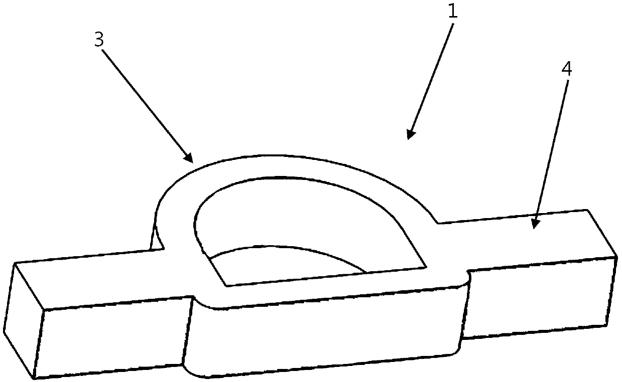
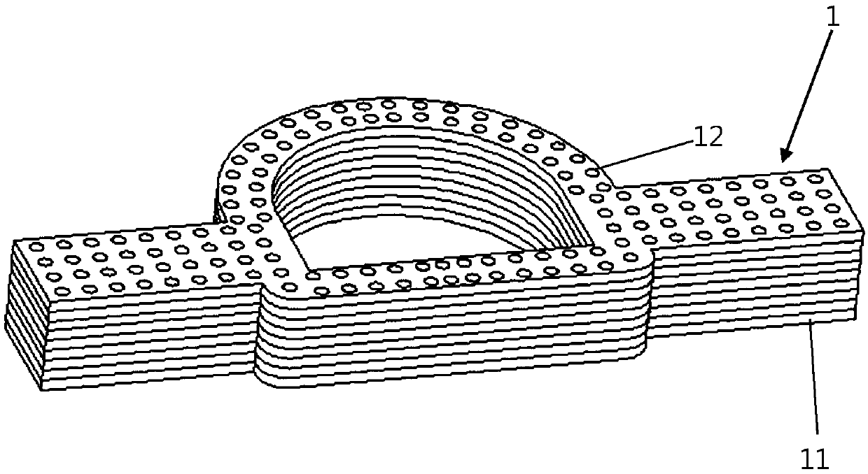
[0043] A profiled three-dimensional fabric 1, see 1 and figure 2 , including a frame body 3 located in the middle and side wings 4 located on both sides of the frame body 3 in the length direction. In this embodiment, the side wings 4 are arranged on opposite sides of the frame body 3, and the side wings 4 on both sides are symmetrical set up. Both the frame body 3 and the side wings 4 are composed of 225 layers of X-Y plane contoured unit layers 11 laminated, and the frame body 3 and side wings 4 are respectively provided with Z-direction fiber bundles 12 penetrating through the X-Y plane contoured unit layers 11 .

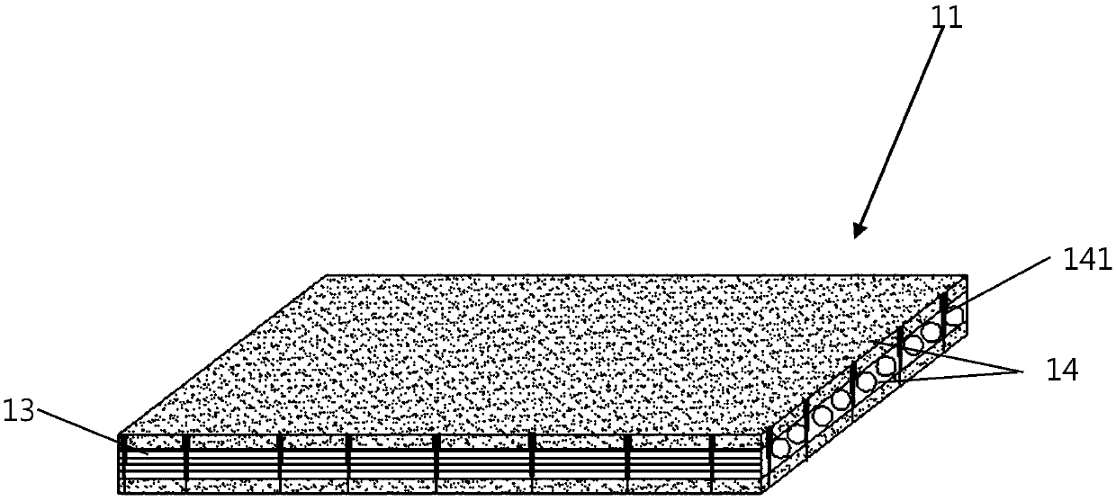
[0044] In this embodiment, the X-Y plane profiling unit layer 11 is composed of two layers of continuous fiber profiling layers 13 and three layers of fiber mat layers 14, and the two layers of continuous fiber profiling layers 13 are respectively arranged as circumferentially arranged Continuous fibers and continuous fibers pointing towards the center. In thi...

Embodiment 2

[0050] The profiling three-dimensional fabric 1 in this embodiment is basically the same as that in Embodiment 1, the difference is that in this embodiment, the frame body 3 and the side wings 4 are formed by stacking 375 layers of X-Y plane profiling unit layers 11 , wherein, the X-Y plane profiling unit layer 11 is formed by one continuous fiber profiling layer 13 and two fiber mat layers 14.

[0051] In this embodiment, please refer to 5, the continuous fiber profiling layer 13 is arranged in the circumferential direction, and the dominant continuous fiber arranged in the circumferential direction is the frame area 131 arranged on the outer periphery of the frame body 3, and the frame area 131 is at the end of the wing 4 The ends are closed one by one from the inside to the outside, and the continuous fiber also includes a side wing middle area 133 arranged on the side wing 4, and the frame area 131 surrounds the side wing middle area 133 inside it and is profiled side by si...

Embodiment 3

[0057] The profiling three-dimensional fabric 1 in this embodiment is basically the same as Embodiment 1 and Embodiment 2, the difference is that in this embodiment, the frame body 3 and the side wings 4 are formed by 192 layers of X-Y plane profiling unit layers 11 Wherein, the X-Y plane profiling unit layer 11 includes two continuous fiber profiling layers 13 and three fiber mat layers 14.

[0058] The two layers of continuous fiber profiling layers 13 are continuous fibers arranged circumferentially and directed to the center respectively. In this embodiment, the continuous fibers directed to the center are the same as in Example 1; please refer to 6. The continuous fibers arranged in the direction include a frame area 131 closed one by one from the inside to the outside at the end of the side wing 4 and a side wing middle area 133 located on the side wing 4, and the frame area 131 is included in the outer periphery of the side wing middle area. In this embodiment, the circ...


PUM


Abstract

The invention provides profiling three-dimensional fabric. The profiling three-dimensional fabric comprises X-Y plane profiling unit layers and Z-direction fiber bundles penetrating through the X-Y plane profiling unit layers. Each X-Y plane profiling unit layer comprises at least one continuous fiber profiling layer and a plurality of fiber mesh felt layers. The multiple X-Y plane profiling unitlayers are stacked in the Z direction. By arranging at least one continuous fiber profiling layer on the X-Y plane profiling unit layers, the profiling continuity of plane fibers of the finally-formedprofiling three-dimensional fabric is good, and the laying mode and the angle of the continuous fibers of the profiling three-dimensional fabric are high in designability; and meanwhile, by arrangingthe Z-direction fiber bundles in a penetrating mode, the X-Y plane profiling unit layers of the adjacent layers are connected and fixed.

Description

technical field [0001] The invention relates to the technical field of composite materials, in particular to a profiled three-dimensional fabric. Background technique [0002] This section is intended to provide a background or context for implementations of the invention that are recited in the claims. The descriptions herein are not admitted to be prior art by inclusion in this section. [0003] The new type of aircraft is flying at hypersonic speed for a long time in the adjacent space. In order to improve its flight speed and performance / function, it is developing in the direction of light weight and high performance. The structure and performance of the material are highly designable and meet the development requirements of new aircraft. Therefore, its load-bearing parts, such as load-bearing frames, rudders, ventral fins, side panels and other special-shaped parts, have gradually changed from metal materials to fiber prefabricated parts. It is a full-composite materi...

Claims


Application Information

Patent Timeline
Patent Type & Authority Applications(China)
IPC IPC(8): D04H1/76D04H1/4209
CPCD04H1/4209D04H1/76
Inventor 缪云良
Owner JIANGSU TIANNIAO HIGH TECH
Why Eureka
Try Eureka