
Pre-stressed anchor cable combined ultrahigh composite reinforced soil abutment and construction method thereof

A technology of prestressed anchor cables and reinforced soil, which is applied in the direction of basic structure engineering, bridges, artificial islands, etc., can solve the problems of increased lateral soil pressure, decreased overall stability and anti-overturning ability of reinforced body structures, and reinforced soil Problems such as abutment slide, to achieve the effect of increasing the height, enhancing the overall stability and anti-overturning ability, and improving the overall stability and anti-overturning ability

Pending Publication Date: 2020-07-28
ZHONGBEI UNIV
View PDF0 Cites 6 Cited by
  • Summary
  • Abstract
  • Description
  • Claims
  • Application Information

AI Technical Summary

Problems solved by technology

[0005] Even so, reinforced earth abutments still have their shortcomings. Traditional reinforced earth abutments are difficult to build superhigh abutments with a height of more than 20 meters. The reinforced body structure composed of material and filling soil can only guarantee its internal stability, while the overall stability and anti-overturning ability of the unreinforced soil body and the entire reinforced body structure are seriously reduced, which is very easy to cause reinforcement. The earth abutment slides along the slope of the mountain; with the increase of the height of the single-stage abutment, the mass of the backfill behind the wall increases continuously, which makes the center of gravity of the backfill rise, the lateral earth pressure increases, and a large bending moment is generated on the bottom panel , causing the wall to bulge, bulge, and even partially crack, break and fall off the panel

Method used


Image

  • Pre-stressed anchor cable combined ultrahigh composite reinforced soil abutment and construction method thereof
  • Pre-stressed anchor cable combined ultrahigh composite reinforced soil abutment and construction method thereof
  • Pre-stressed anchor cable combined ultrahigh composite reinforced soil abutment and construction method thereof

Examples


Embodiment Construction

[0057] The present invention will be further described in detail below in conjunction with specific embodiments, but the protection scope of the present invention is not limited to these embodiments, and all changes or equivalent substitutions that do not depart from the concept of the present invention are included within the protection scope of the present invention.

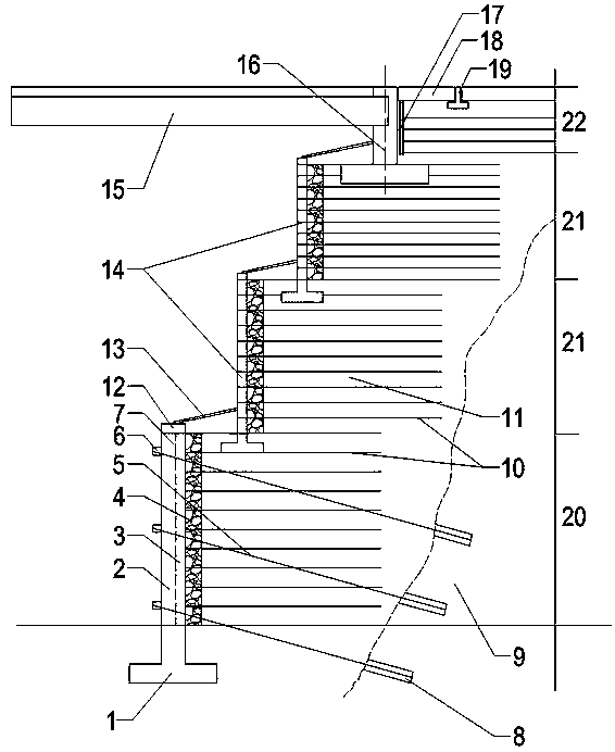
[0058] The ultra-high composite reinforced soil abutment combined with prestressed anchor cables includes the lowest abutment 20 leaning against the mountain 9, the uppermost abutment 22 and other abutments 21 at various levels.

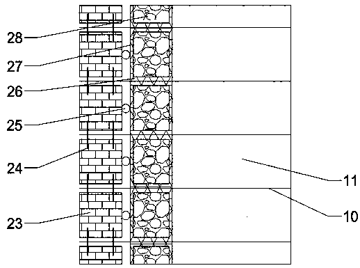
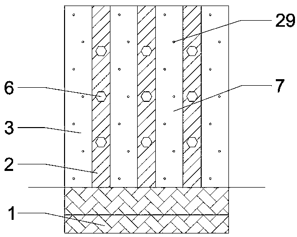
[0059] The lowermost abutment 20 includes a reinforced body structure constructed of several equally spaced geogrids 10 and wall fillers 11. The outer side of the geogrid 10 away from the side of the mountain body 9 is provided with an anti-filter layer 4, and the anti-filter layer 4 A retaining wall 7 is arranged on the outer side, a reinforced concrete cover beam 12 is arranged on t...


PUM


Abstract

The invention discloses a pre-stressed anchor cable combined ultrahigh composite reinforced soil abutment and a construction method thereof. The ultrahigh composite reinforced soil abutment is structurally provided with multiple stages of abutment bodies from top to bottom. Geogrids with equal intervals are laid on each stage of abutment, an inverted filter layer formed by piling up geogrids whichare filled with gravels and wrapped by geotextile is arranged at the side close to a panel, a reinforced concrete panel is arranged outside the inverted filter layer, a reinforced concrete horizontalcushion layer is arranged in the lower portion of the panel of each stage of abutment and buried for a certain depth, and a concrete bent cap is arranged in the upper portion. According to the composite reinforced soil abutment, pre-stressed anchor cables anchored into the mountain rock stratum are combined with the lowest-stage abutment, the overall stability and the anti-overturning capacity ofan unreinforced soil body and the whole reinforced body structure are greatly improved, and the constraint of the pre-stressed anchor cables on the retaining wall body can further effectively resistthe bending moment of lateral soil pressure from backfill behind the wall on a bottom-layer panel of the abutment.

Description

technical field [0001] The invention relates to a super-high composite reinforced soil abutment combined with prestressed anchor cables and a construction method thereof, belonging to the technical field of geotechnical engineering. Background technique [0002] Modern reinforced soil technology originated in France in the 1960s. It was mainly used in retaining walls in the early days. With the continuous development of this technology, it has gradually been applied to places that need to bear heavy loads, such as rail transit, industrial buildings and highway etc. Especially in recent years, the application of reinforced soil technology on abutments has developed rapidly in some developed countries in Europe and America. [0003] The reinforced soil abutment is a reinforced body structure composed of reinforcement, backfill and retaining wall panels. The reinforcement is placed between the fillings to overcome the weakness of the soil itself in terms of low tensile strengt...

Claims


Application Information

Patent Timeline
IPC IPC(8): E01D19/02E02D29/02E02D5/76E01D19/04E01D19/00E01D21/00
CPCE01D19/00E01D19/02E01D19/04E01D21/00E02D5/76E02D29/02E02D29/0233E02D29/0241
Inventor 董彦莉李建达赵致艺郭鹏飞高慧芳裴伟鹏张梦琪韩云山郑利锋张晓双张兆鹏王元龙刘亚玲张洪萍周敏
Owner ZHONGBEI UNIV
Learn More