Hedging type flood discharging and energy dissipation structure and method

A hedging and flood discharge technology, which is applied in water conservancy projects, sea area projects, coastline protection, etc., can solve problems such as scour damage to the bottom plate of stilling pools, high water flow velocity, and endanger the safety of downstream buildings, so as to reduce the scouring force and extend the The effect of service life and energy dissipation efficiency improvement

Inactive Publication Date: 2020-07-28
CHINA POWER CONSRTUCTION GRP GUIYANG SURVEY & DESIGN INST CO LTD
View PDF6 Cites 4 Cited by
  • Summary
  • Abstract
  • Description
  • Claims
  • Application Information

AI Technical Summary

Problems solved by technology

[0002] In recent decades, domestic water conservancy and hydropower construction has developed rapidly, and downstream energy dissipation and anti-scour buildings are one of the important parts that affect the safe operation of hydropower projects. Therefore, flood discharge and energy dissipation are very prominent key technical issues. Flow energy dissipation, bottom flow energy dissipation, and surface flow energy dissipation, the water flow velocity at the outlet of the discharge structure is high and the kinetic energy is large, which will cause serious erosion deformation to the downstream riverbed and bank slope, endangering the safety of downstream buildings
When the high-speed and strong turbulent water flows through the stilling basin, it is easy to cause serious erosion damage to the bottom plate of the stilling basin

Method used


Image

  • Hedging type flood discharging and energy dissipation structure and method
  • Hedging type flood discharging and energy dissipation structure and method

Examples


Embodiment Construction

[0016] The technical solution of the present invention is further described below in conjunction with the accompanying drawings, but the scope of protection is not limited to the description.

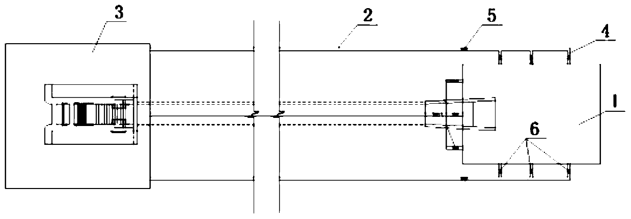
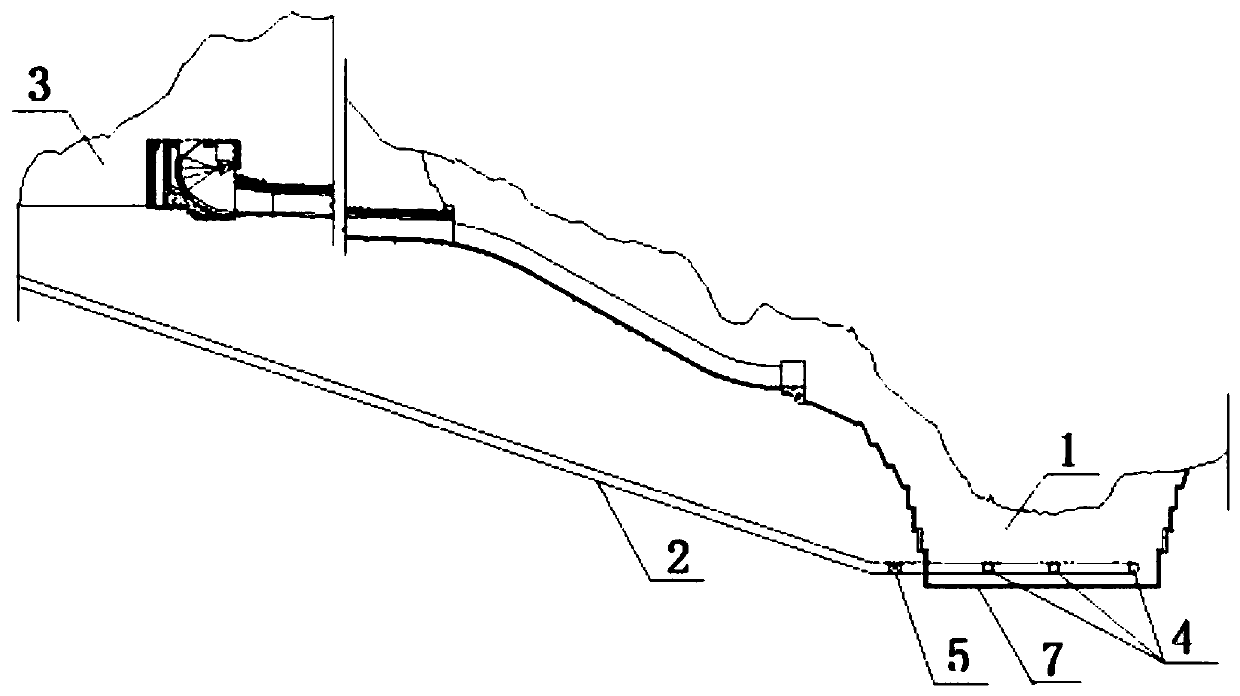
[0017] Such as figure 1 , figure 2 As shown, the present invention provides a hedging flood discharge energy dissipation structure, including a stilling basin 1, and a tunnel 2 is arranged on the periphery of the stilling basin 1, the number of the tunnels 2 is an even number, one end of the tunnel 2 communicates with the reservoir 3, and The other end communicates with two inner side walls of the stilling basin 1 opposite to each other through branch pipes 4 .

[0018] Further, the number of branch pipes 4 connected on the two inner side walls opposite to each other of the stilling basin 1 is the same. Preferably, the number of branch pipes 4 is multiple, and multiple branch pipes 4 are deployed in parallel.

[0019] In addition, a valve A5 is installed above the tunnel 2, and the ...


PUM


Abstract

The invention discloses a hedging type flood discharging and energy dissipation structure and method. The hedging type flood discharging and energy dissipation structure comprises a stilling basin, atunnel is arranged on the periphery of the stilling basin, one end of the tunnel communicates with a reservoir, and the other end of the tunnel correspondingly communicates with two opposite inner side walls of the stilling basin through branched pipes. By adopting the technical scheme of the hedging type flood discharging and energy dissipation structure, during the flood discharging of the reservoir, a valve A and a valve B are opened, so that water flow in the reservoir flows into the stilling basin sequentially through the tunnel, the branched pipes and the two opposite inner side walls ofthe stilling basin, the water flow mutually hedges and collides a flood discharging water tongue in the stilling basin, energy of the flood discharging water tongue and own jet flow is dissipated inthe collision process, and then the water flow falls to the bottom of the stilling basin. A water cushion is arranged at the bottom of the stilling basin to eliminate the rest energy in the water flow, so that the energy in the water flow is sufficiently dissipated, the washing of an underwater bed, a bank slope and other buildings is reduced, the energy dissipation efficiency is improved, the safety of the downstream buildings is ensured, and the washing action force of the water cushion is reduced.

Description

technical field [0001] The invention specifically relates to the technical field of water conservancy and hydropower engineering, in particular to a hedging flood discharge energy dissipation structure and method. Background technique [0002] In recent decades, domestic water conservancy and hydropower construction has developed rapidly, and downstream energy dissipation and anti-scour buildings are one of the important parts that affect the safe operation of hydropower projects. Therefore, flood discharge and energy dissipation are very prominent key technical issues. Flow energy dissipation, bottom flow energy dissipation, and surface flow energy dissipation, the water flow velocity at the outlet of the drainage structure is high and the kinetic energy is large, which will cause serious erosion deformation to the downstream riverbed and bank slope, endangering the safety of downstream buildings. When the high-speed and strong turbulent water flows through the stilling bas...

Claims


Application Information

Patent Timeline
Patent Type & Authority Applications(China)
IPC IPC(8): E02B8/06E02B8/04
CPCE02B8/04E02B8/06
Inventor 鲍伟杜帅群郑雪玉
Owner CHINA POWER CONSRTUCTION GRP GUIYANG SURVEY & DESIGN INST CO LTD
Why Eureka
Try Eureka