Supercharge Your Innovation With Domain-Expert AI Agents!

Liftable multimedia projection equipment

A projection equipment, multimedia technology, applied in mechanical equipment, optics, instruments, etc., to achieve the effect of a wide range of heights and a good sense of visual experience

Inactive Publication Date: 2020-07-28
常小兵
View PDF0 Cites 8 Cited by
  • Summary
  • Abstract
  • Description
  • Claims
  • Application Information

AI Technical Summary

Problems solved by technology

[0003] Traditional multimedia projection equipment can only be fixed at the same position for projection. For different indoor environments, sometimes it is necessary to adjust the projection equipment to a suitable height to obtain a better visual experience

Method used


Image

  • Liftable multimedia projection equipment
  • Liftable multimedia projection equipment
  • Liftable multimedia projection equipment

Examples


Embodiment 1

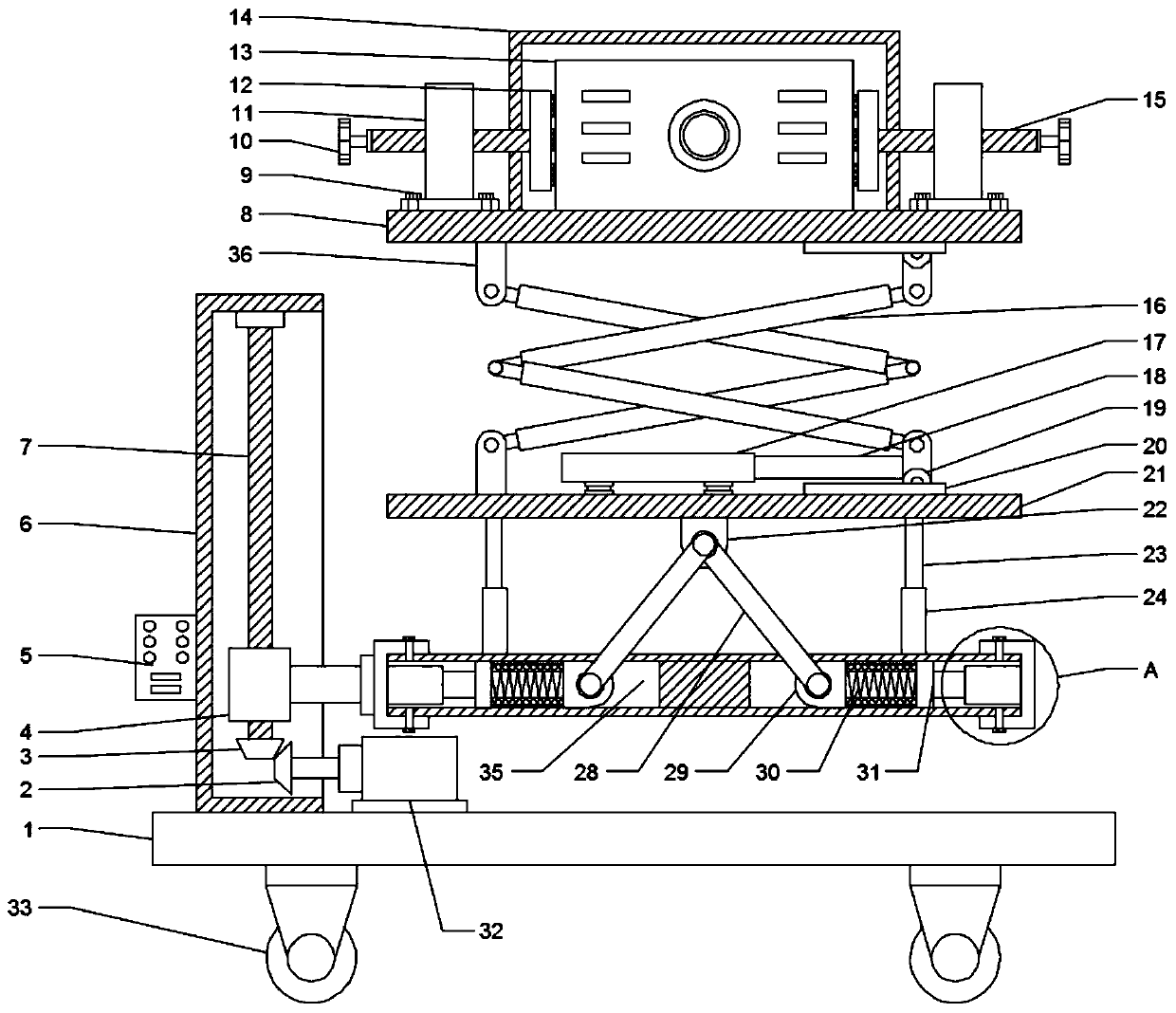
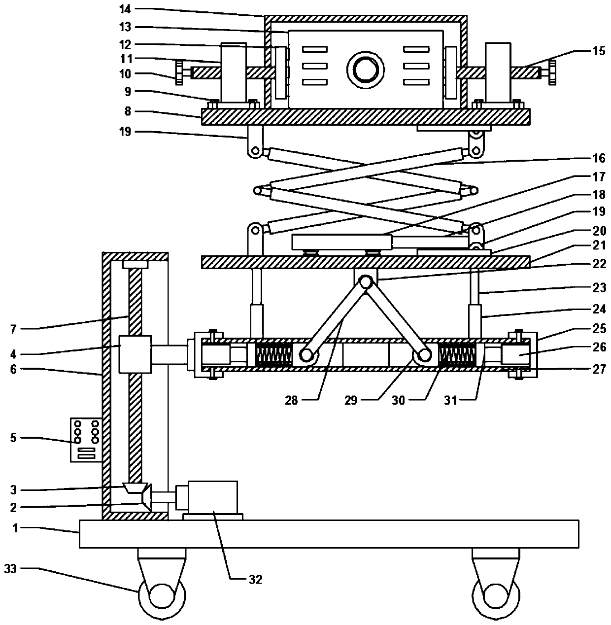
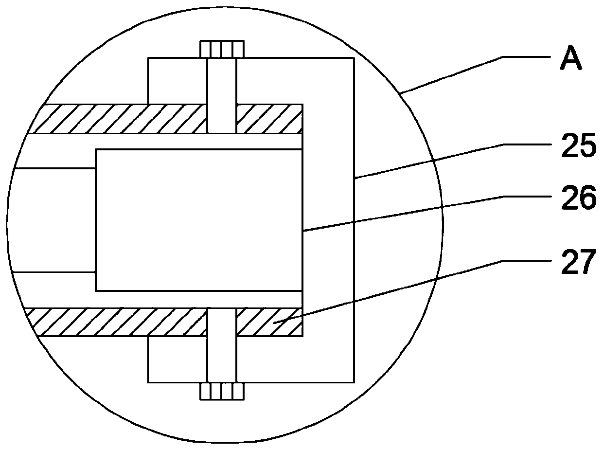
[0023] see Figure 1-4 , a liftable multimedia projection device, including a support frame 1 and a projection device 13, a motor 32 is installed on the top surface of the support frame 1, the motor 32 is connected to the support frame 1 by bolts, and the output end of the motor 32 is connected to a bevel gear One 2, the lifting box 6 is installed on the left side of the motor 32, the lifting box 6 is welded on the surface of the support frame 1, the screw rod 7 is installed in the lifting box 6, and the top of the screw rod 7 is connected to the lifting box body 6. The inner wall is connected by a rotating bearing. The bottom end of the screw rod 7 is connected to the second bevel gear 3. The first bevel gear 2 meshes with the second bevel gear 3. The movable seat 4 is installed on the surface of the screw rod 7, and the movable seat 4 is fixed. Connect the fastening seat 25, the cylinder box 27 is installed in the fastening seat 25, the fastening seat 25 on the left and righ...

Embodiment 2

[0029] see Figure 1-5 , on the basis of Embodiment 1, in order to fix the projection device, the left and right sides of the support plate 8 are fixed with a support 11, a screw 15 is installed in the support 11, and a rotating handle 10 is installed at the end of the screw 15 The clamp 12 is fixed at the end of the screw 15 away from the rotating handle 10. By rotating the rotating handle 10, the screw 15 pushes the left and right clamps and moves inwardly to fix the projection device 13 on the surface of the support plate 8.

[0030] Further, in order to fix the support 11 , in this embodiment, the support 11 is detachably connected to the support plate 8 through fastening bolts 9 .

[0031] Further, in order to prevent the projection device 13 from dust falling into the projection device during operation and affecting the operation of the device, in this embodiment, a dust-proof box 14 is installed on the outside of the projection device 13, and the dust-proof box 14 is in...


PUM


Abstract

The invention discloses liftable multimedia projection equipment, and relates to the technical field of multimedia equipment. The equipment comprises a support frame and a projection equipment body, wherein a motor is mounted to the top surface of the support frame, and is connected to the support frame through a bolt, the output end of the motor is connected to a bevel gear I, a lifting box is mounted to the left side of the motor, a screw rod is mounted inside the lifting box, the bottom end of the screw rod is connected to a bevel gear II, and a moving seat is mounted on the surface of thescrew rod. According to the equipment, the motor drives the bevel gear I to rotate, the bevel gear I drives the bevel gear II and the screw rod to rotate, the moving seat pushes a fastening seat and acylinder box to move in the vertical direction, the cylinder drives a telescopic rod I to stretch and contract, the telescopic rod I pushes hinge seats on the left and right ends of the telescopic rod to move inwards or outwards simultaneously, a push rod pushes the hinge seat II and a base to ascend or descend, a hydraulic cylinder pushes the telescopic rod II and a pulley to move horizontally in a sliding rail, the pulley drives a cross lifting rod and a supporting plate to ascend or descend, thus realizing the height adjustment of the projection equipment.

Description

technical field [0001] The invention relates to the technical field of multimedia equipment, in particular to a liftable multimedia projection equipment. Background technique [0002] A projector, also known as a projector, is a device that can project images or videos onto a screen. It can be connected to a computer, VCD, DVD, BD, game console, DV, etc. through different interfaces to play the corresponding video signal. Projectors are widely used in homes, offices, schools, and entertainment venues. According to different working methods, there are different types such as CRT, LCD, and DLP. According to their projection methods, they are divided into vertical projectors and horizontal projectors. According to their comparison Different standards are divided into contour projectors and digital projectors. [0003] Traditional multimedia projection equipment can only be fixed at the same location for projection. For different indoor environments, sometimes it is necessary t...

Claims


Application Information

Patent Timeline
Patent Type & Authority Applications(China)
IPC IPC(8): F16M11/04F16M11/18F16M11/38F16M11/42G03B21/14
CPCF16M11/046F16M11/18F16M11/38F16M11/42G03B21/145
Inventor 常小兵
Owner 常小兵
Features
  • R&D
  • Intellectual Property
  • Life Sciences
  • Materials
  • Tech Scout
  • Unparalleled Data Quality
  • Higher Quality Content
  • 60% Fewer Hallucinations
Learn More