Battery cell modeling method

A modeling method and cell technology, which is applied in structured data retrieval, database design/maintenance, design optimization/simulation, etc., can solve the problems of insufficient local accuracy, lack of equivalent mechanical models of cells, and simulation model safety issues that cannot be done More accurate reliability assessment and other issues

Active Publication Date: 2020-07-28
MICROVAST POWER SYST CO LTD
View PDF4 Cites 4 Cited by
  • Summary
  • Abstract
  • Description
  • Claims
  • Application Information

AI Technical Summary

Problems solved by technology

[0003] Therefore, at present, the simulation modeling of battery packs based on CAE technology has the problem of insufficient local accuracy, and lacks an accurate equivalent mechanical model of batteries. When the battery pack is subjected to mechanical abuse such as extrusion, the simulation model will It is impossible to make a more accurate reliability assessment of the core security issues

Method used


Image

  • Battery cell modeling method
  • Battery cell modeling method
  • Battery cell modeling method

Examples


Embodiment 1

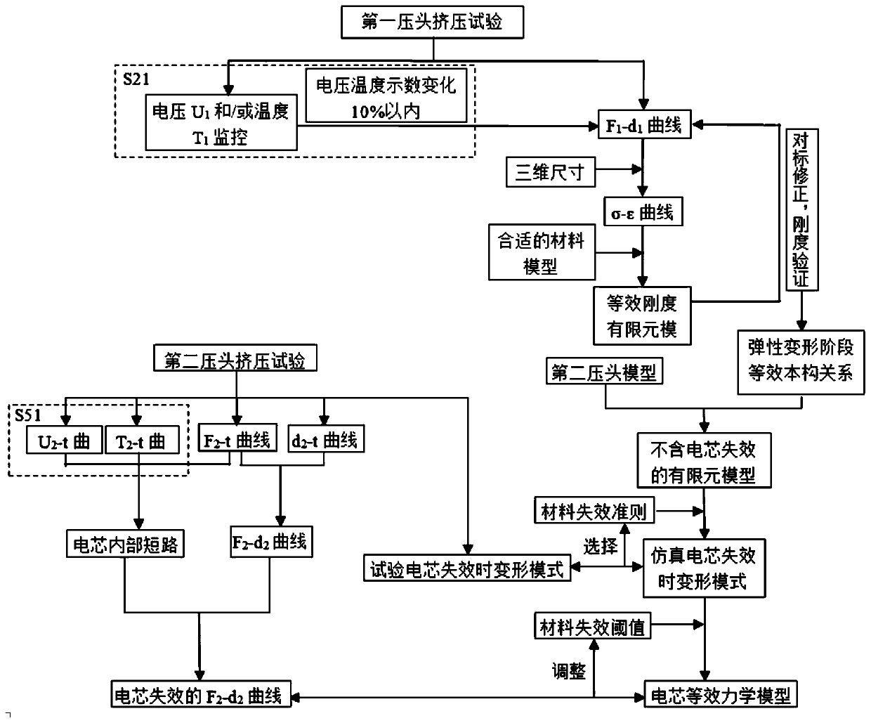
[0043] Such as figure 1 As shown in the process content other than the dotted box, this embodiment provides a method for modeling the battery cell 10, including the following steps:

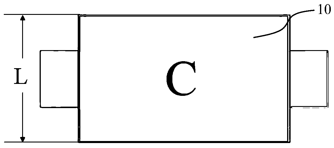
[0044] S1: Use a micrometer to measure the three-dimensional size of the battery core 10, including the thickness H of the battery core 10 and the area S of the C surface perpendicular to the thickness direction (such as figure 2 shown); the battery core 10 is a rectangular parallelepiped structure with a measured length of 59.50mm, a width of 34.00mm, and a thickness of 5.35mm. Therefore, the area S=59.5mm×34mm=202.3mm 2 , thickness H=5.35mm; the initial SOC of the battery cell 10 is 10%.

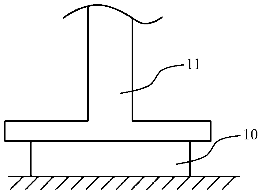
[0045] S2: Use the first indenter 11 to squeeze the battery core 10 at a rate of 1mm / min along the thickness direction (such as image 3 shown), the contact surface between the first indenter 11 and the C surface is a plane and the size is greater than or equal to the C surface, and the compressive deforma...

Embodiment 2

[0051] Same as Example 1, the difference is that the initial SOC of the battery cell 10 is 20%, and the step S2 also includes a step S21: monitoring the voltage U of the battery cell 10 during extrusion 1 and / or temperature T 1 As time changes, since the thickness of the tabs is smaller than the thickness of the cell 10, the two ends of the voltage sensor are connected to the two tabs of the cell 10 respectively, and the thermocouple is connected to any one of the tabs. When the voltage U 1 drop by more than 10% and / or temperature T 1 When the rise exceeds 10%, stop squeezing. When the voltage U 1 drop within 10% or temperature T 1 When the increase is within 10%, it is considered that the battery cell 10 has no internal short circuit or thermal runaway, that is, the internal structure and material of the battery cell 10 have not failed, and are in the elastic-plastic stage. Therefore, the battery cell 10 is in the elastic-plastic stage F 1 -d 1 The curve is the equivale...

Embodiment 3

[0053] Same as in Embodiment 1, the difference is that the step S5 also includes a step S51: monitoring the voltage U of the battery cell 10 during the extrusion process 2 and / or temperature T 2 , when the voltage U 2 drops by more than 15% and / or the temperature T 2 When the rise exceeds 15%, stop squeezing. Since the second indenter 12 squeezes the cell 10, the cell 10 is in a local stress state, so a small extrusion force will cause the cell 10 to fail, and material failure will cause the nonlinearity of the structure and the bearing capacity. Decline. When an internal short circuit occurs in the cell 10, the voltage U of the cell 10 2 drop, temperature T 2 rise. Therefore, by monitoring the temperature T 2 , voltage U 2 and contact load F 2 At least one of the values ​​in the value can determine the failure moment of the battery cell 10, and read the peak load F at the time of failure max , get with contact load F 2 F in descending segment 2 -d 2 curve, the F ...


PUM


Abstract

The invention provides a battery cell modeling method. The battery cell modeling method comprises the following steps: S1, measuring the three-dimensional size of a battery cell; S2, extruding the battery cell along the thickness direction by adopting a first pressure head to obtain an F1-d1 curve of the battery cell; S3, calculating an equivalent sigma-epsilon curve of the battery cell; S4, selecting an equivalent material according to the equivalent sigma-epsilon curve, endowing parameters of the equivalent material to the battery cell model, performing benchmarking correction on a simulation curve F1'-d1' curve when the battery cell model is extruded by a first pressure head model, and establishing an equivalent stiffness finite element model of the battery cell; S5, extruding the battery cell along the thickness direction by adopting a second pressure head to obtain an F2-d2 curve; and S6, on the basis of the step S4, replacing the first pressure head model with a second pressure head model for simulation and benchmarking correction, and establishing a final battery cell equivalent mechanical model. According to the battery cell equivalent mechanical model established by the method, the simulation precision of the battery pack can be improved, the stress of the battery cell is evaluated more accurately by utilizing a simulation means, and the evaluation capability of the CAE technology on the safety of the battery pack is expanded.

Description

technical field [0001] The invention relates to a battery modeling method, in particular to a modeling method of a battery equivalent mechanical model based on CAE technology. Background technique [0002] The structure of the cell is relatively complex, and its interior is a multi-layer thin film layer structure. The thickness of the film is on the order of microns, while the length and width of the cell are on the order of decimeters, and the positive electrode, negative electrode and diaphragm in the film The mechanical properties are different. Therefore, the structure of the cell is characterized by cross-scale and containing multiple materials. In order to facilitate engineering calculations, the current safety evaluation of battery packs based on CAE technology is limited to some important components. In the structural simulation of the battery pack, the module is generally simplified into a mass point or a mass block, lacking more accurate cell parameter input, and...

Claims


Application Information

Patent Timeline
Patent Type & Authority Applications(China)
IPC IPC(8): G06F16/21G06F30/20
CPCY02E60/10
Inventor 王艳龙刘文峰方伟峰文娟·刘·麦蒂斯
Owner MICROVAST POWER SYST CO LTD
Why Eureka
Try Eureka