Change-over switch
A technology for switching switches and supporting structures. It is applied in the direction of electric switches, electrical components, circuits, etc. It can solve the problems of short service life, low mechanical strength, and insufficient fastening and firmness, and achieve reliable positioning, extended service life, and good mechanical properties. Effect
- Summary
- Abstract
- Description
- Claims
- Application Information
AI Technical Summary
Problems solved by technology
Method used
Image

Examples
Embodiment 1
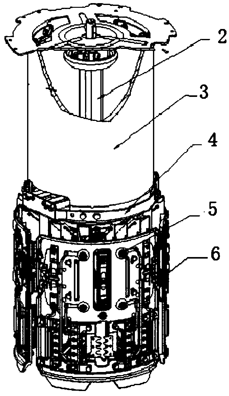
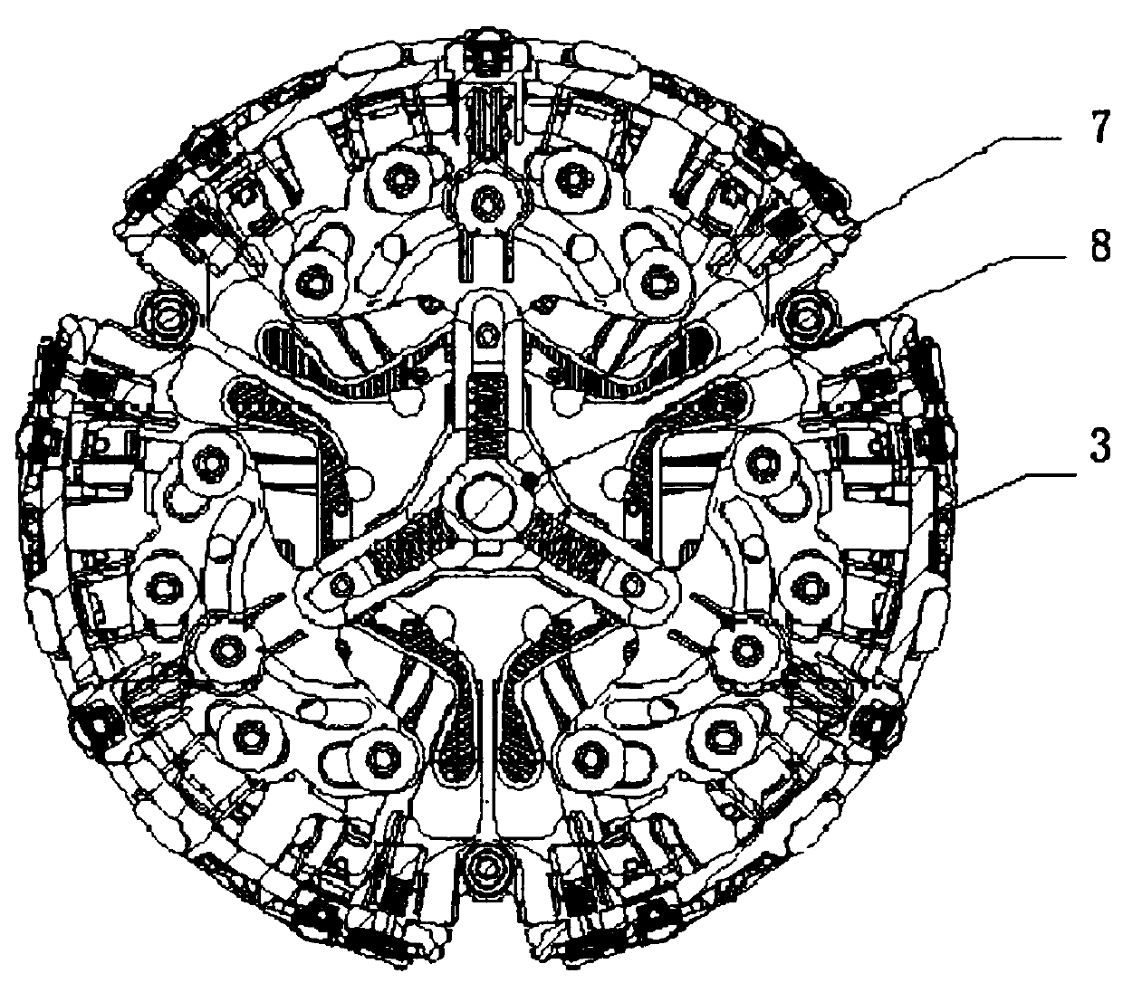
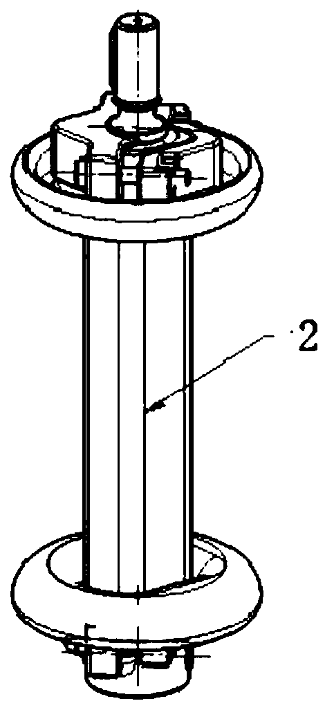
[0021] see Figure 1-6 , the present invention provides a technical solution: a diverter switch, including epoxy glass fiber extrusion rod 2, diverter switch support structure 3, fast mechanism bottom plate 4, diverter switch dynamic arc contact bracket 5, static arc contact installation and fixing mechanism 6. The diverter switch support structure 3 is provided with a diverter switch dynamic main contact 7 and a rotating bracket 8. The epoxy glass fiber extruded rod 2 is located inside the diverter switch support structure 3. The quick mechanism bottom plate 4 and the diverter switch dynamic arc contact bracket 5 Set on the diverter switch support structure 3, the diverter switch support structure 3 is provided with the diverter switch moving main contact 7 and the rotating bracket 8, the quick mechanism bottom plate 4 is formed by the integral flanging of metal parts, and the thickness of the rotating bracket 8 is 9.5mm , the static arc contact installation and fixing mechan...
Embodiment 2
[0026] The present invention provides a technical solution: a switch, including epoxy glass fiber extrusion rod 2, switch support structure 3, fast mechanism bottom plate 4, switch switch dynamic arc contact bracket 5, static arc contact installation and fixing mechanism 6 , the diverter switch support structure 3 is provided with a diverter switch moving main contact 7 and a rotating bracket 8, the epoxy glass fiber extruded rod 2 is located inside the diverter switch support structure 3, the quick mechanism bottom plate 4 and the diverter switch moving arc contact bracket 5 are set On the diverter switch support structure 3, the diverter switch support structure 3 is provided with a diverter switch movable main contact 7 and a rotating bracket 8, the quick mechanism bottom plate 4 is formed by stretching and flanging the metal parts as a whole, and the thickness of the rotating bracket 8 is 9.5 mm. The static arc contact installation and fixing mechanism 6 includes a screw-sh...
Embodiment 3
[0031] The present invention provides a technical solution: a switch, including epoxy glass fiber extrusion rod 2, switch support structure 3, fast mechanism bottom plate 4, switch switch dynamic arc contact bracket 5, static arc contact installation and fixing mechanism 6 , the diverter switch support structure 3 is provided with a diverter switch moving main contact 7 and a rotating bracket 8, the epoxy glass fiber extruded rod 2 is located inside the diverter switch support structure 3, the quick mechanism bottom plate 4 and the diverter switch moving arc contact bracket 5 are set On the diverter switch support structure 3, the diverter switch support structure 3 is provided with a diverter switch movable main contact 7 and a rotating bracket 8, the quick mechanism bottom plate 4 is formed by stretching and flanging the metal parts as a whole, and the thickness of the rotating bracket 8 is 9.5 mm. The static arc contact installation and fixing mechanism 6 includes a screw-sh...
PUM
| Property | Measurement | Unit |
|---|---|---|
| Thickness | aaaaa | aaaaa |
Abstract
Description
Claims
Application Information
 - R&D
- Intellectual Property
- Life Sciences
- Materials
- Tech Scout
- Unparalleled Data Quality
- Higher Quality Content
- 60% Fewer Hallucinations
Browse by: Latest US Patents, China's latest patents, Technical Efficacy Thesaurus, Application Domain, Technology Topic, Popular Technical Reports.
© 2025 PatSnap. All rights reserved.Legal|Privacy policy|Modern Slavery Act Transparency Statement|Sitemap|About US| Contact US: help@patsnap.com