End plate wire fixer

A wire fixer and end plate technology, applied in the direction of electrical components, connections, clamping/spring connections, etc., can solve problems such as poor contact between wires and wire clamps, unsteady tightening torque, and ineffective compression of wires. Achieve the effect of saving process, reducing processing cost and stabilizing tightening torque

Active Publication Date: 2021-09-03
CHONGQING DEEPU ELECTRIC
View PDF6 Cites 0 Cited by
  • Summary
  • Abstract
  • Description
  • Claims
  • Application Information

AI Technical Summary

Problems solved by technology

[0005] 1. Although a certain tightening torque is maintained when the nut is used for locking installation, the tightening torque is often not constant. Even if the torque nut has been used, there is still a situation where the wire cannot be effectively compressed, resulting in the contact between the wire and the clamp Defective and affect the safe operation of the power grid
[0006] 2. The end plate head protruding from one or both ends of the lower splint occupies a large volume, which not only makes the end plate wire fixer much heavier as a whole, but also requires a lot of cutting on the basis of the original lower end plate blank , grinding and other processes, the processing cost is relatively high

Method used


Image

  • End plate wire fixer
  • End plate wire fixer
  • End plate wire fixer

Examples


Embodiment 1

[0032] It should be noted in advance that in the present invention, unless otherwise specified and limited, the terms "installation", "connection", "connection", "fixation" and other terms should be understood in a broad sense, for example, it can be a fixed connection, It can also be detachably connected or integrally connected; it can be directly connected or indirectly connected through an intermediary, and it can be internal communication between two components. Those of ordinary skill in the art can understand the specific meanings of the above terms in the present invention according to specific situations.

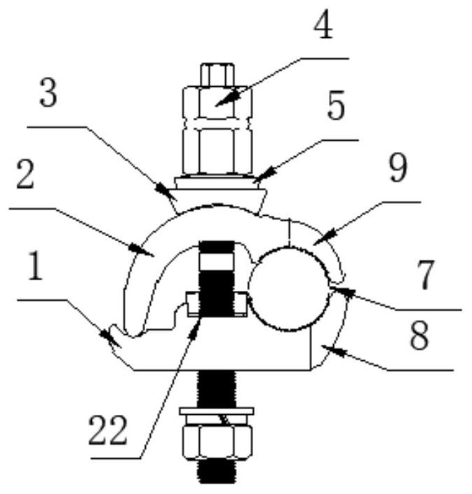
[0033] like Figure 1-Figure 9As shown: this embodiment provides an end plate wire fixer, which includes an upper splint 2, a lower splint 1 and a bolt connection assembly that are fastened to each other. The lower surface of the lower splint 1 is directly in contact with the surface of the end plate 25 of the electrical equipment One side of the upper splint 2 and...

Embodiment 2

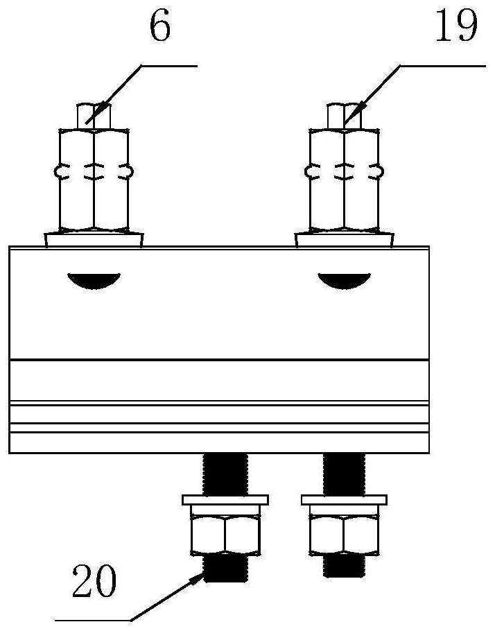
[0039] The main difference from Embodiment 1 is that the threaded hole 24 connected to the third screw 6 is processed as a through hole, and the lower part of the through hole needs to be provided with a protrusion capable of blocking and lifting the third screw. The raised portion can be realized by a size variation of the aperture or a difference in the shape of the aperture.

Embodiment 3

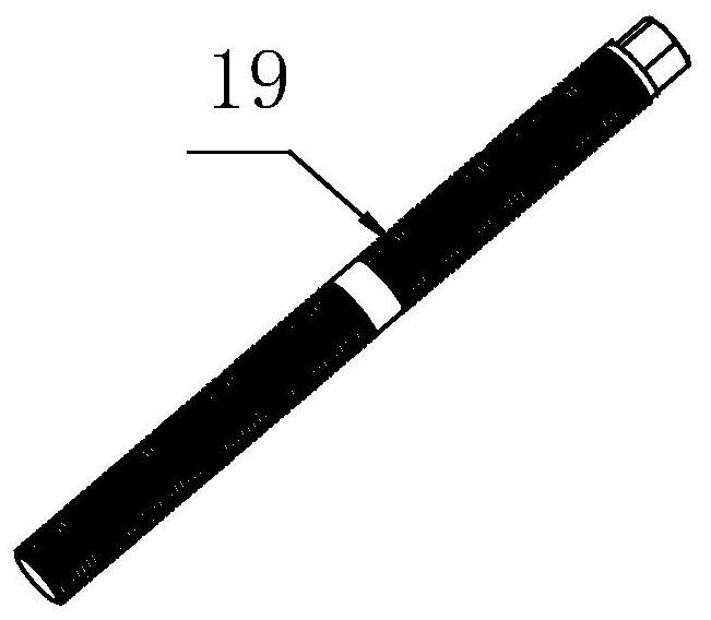
[0041] The main difference from Example 1 is that the first screw and the third screw adopt a stepped shaft shape with a large top and a small bottom, that is, the outer diameter of the lower threaded part of the first screw and the third screw is smaller than that of the upper part.


PUM


Abstract

The invention relates to the field of power wire connection equipment, in particular to an end plate wire fixer; it comprises an upper clamp plate, a lower clamp plate, an arc-shaped washer, a torque nut, a disc spring washer and a screw rod; the arc-shaped washers are buckled with each other There are toothed arc grooves on the clamping wire, the upper splint and the lower splint respectively, the bottom of the lower splint is provided with a threaded hole, the threaded hole cooperates with the screw to lock the fixed screw, and the upper surface of the upper splint is arc-shaped , which is provided with a hole for the screw to pass through, the lower surface of the arc-shaped gasket is designed with an arc that matches the upper surface of the upper splint, and the arc-shaped gasket is provided with a hole for the screw to pass through. The moment nut is located above the arc-shaped washer and connected with the screw rod; the end plate wire fixing device of this technical solution has a large holding area when the wire is clamped, and is reliable and versatile.

Description

technical field [0001] The invention relates to the field of electric wire connection equipment, in particular to an end plate wire fixer. Background technique [0002] Power connection fittings are commonly used devices when circuit breakers, isolating switches, fuses, transformers and other electrical equipment are connected to wires, and play a very important role. [0003] At present, the most common power connection fittings are flat bolt-fastened equipment connection clamps, such as the clamps announced in the comparative document CN202259748U, which include upper and lower splints that are interlocked to realize wire clamping. The clamp body is Made of non-magnetic aluminum alloy, one side of the upper splint is provided with two downward-curved claw-shaped structures along the clamping direction, and one side of the corresponding lower splint is provided with three upward-curved claw-shaped structures, the same The distance between the adjacent claw-shaped structure...

Claims


Application Information

Patent Timeline
Patent Type & Authority Patents(China)
IPC IPC(8): H01R11/09H01R4/44
CPCH01R4/44H01R11/09
Inventor 刘克军
Owner CHONGQING DEEPU ELECTRIC
Why Eureka
Try Eureka