Method and system for removing interference signals in overcurrent protection

A technology of interference signal and overcurrent protection, applied in the protection of overcurrent response, emergency protection circuit devices, components of emergency protection devices, etc., can solve the problems affecting the accuracy of overcurrent protection, judgment errors, etc. Avoid misjudgment, improve work efficiency, avoid the effect of shutdown protection

Active Publication Date: 2020-07-28
HUNAN SANY INTELLIGENT CONTROL EQUIP
View PDF4 Cites 0 Cited by
  • Summary
  • Abstract
  • Description
  • Claims
  • Application Information

AI Technical Summary

Problems solved by technology

Interference signals will bring judgment errors and affect the accuracy of overcurrent protection judgments
cause unnecessary overcurrent protection operation

Method used


Image

  • Method and system for removing interference signals in overcurrent protection
  • Method and system for removing interference signals in overcurrent protection
  • Method and system for removing interference signals in overcurrent protection

Examples


Embodiment 1

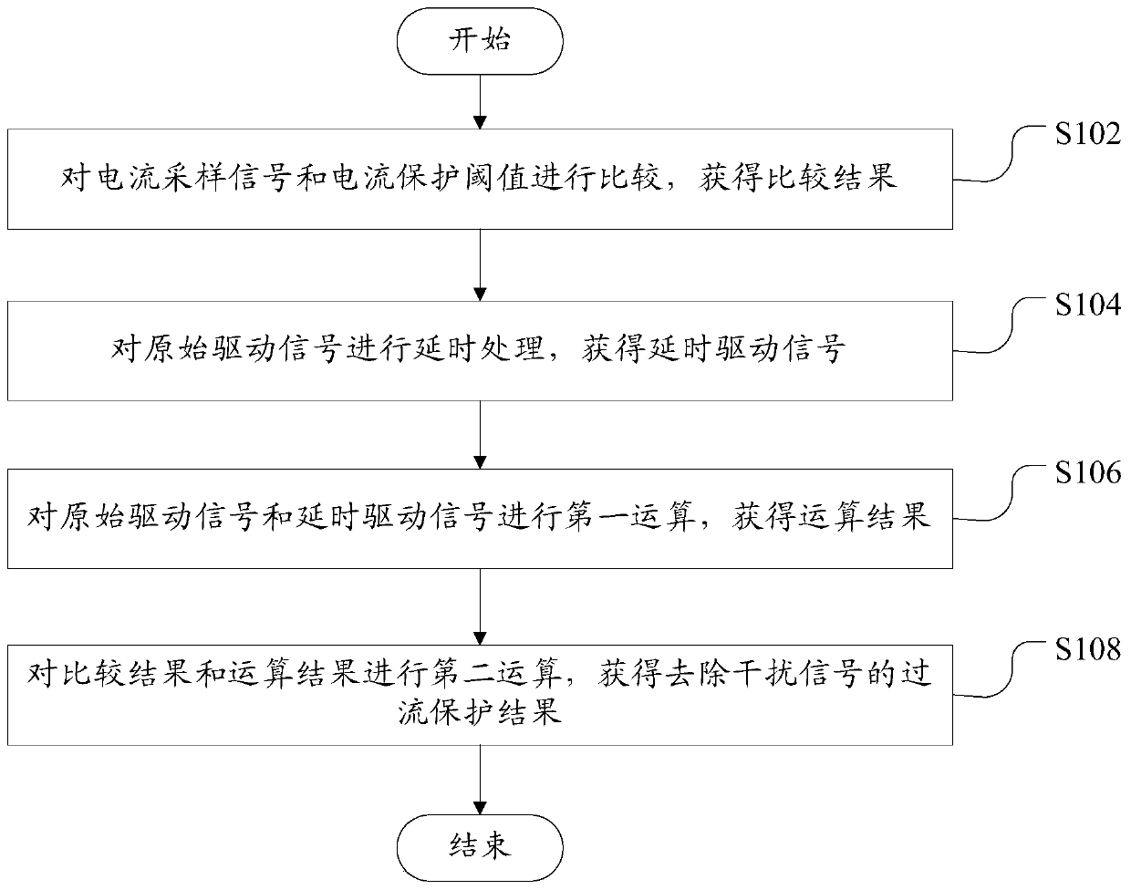
[0041] Such as figure 1 As shown, this embodiment provides a method for removing interference signals in overcurrent protection, including the following steps:

[0042] Step S102, comparing the current sampling signal with the current protection threshold to obtain a comparison result;

[0043] Step S104, performing delay processing on the original driving signal to obtain the delayed driving signal;

[0044] Step S106, performing a first calculation on the original driving signal and the delayed driving signal to obtain a calculation result;

[0045] Step S108, performing a second calculation on the comparison result and the calculation result to obtain an overcurrent protection result with the interference signal removed.

[0046]In this embodiment, the current sampling signal can be measured by hardware such as a sampling resistor, and the current protection threshold is set and adjusted by those skilled in the art according to actual needs. The original drive signal is ...

Embodiment 2

[0050] This embodiment provides a method for removing interference signals in overcurrent protection. In addition to the technical features of Embodiment 1 above, this embodiment further includes the following technical features.

[0051] Delaying the original driving signal to obtain the delayed driving signal specifically includes the following steps: according to the size of the interference signal in the current sampling signal, determine the delay time of the delay processing; according to the delay time, delay the original driving signal processing to obtain the delayed driving signal.

[0052] In other words, in this embodiment, the delay processing time is determined by the size of the interference signal in the current sampling signal. When the interference signal in the current sampling signal is large, the delay processing time can be appropriately increased to ensure that the interference signal Perform complete filtration. When the interference signal in the curr...

Embodiment 3

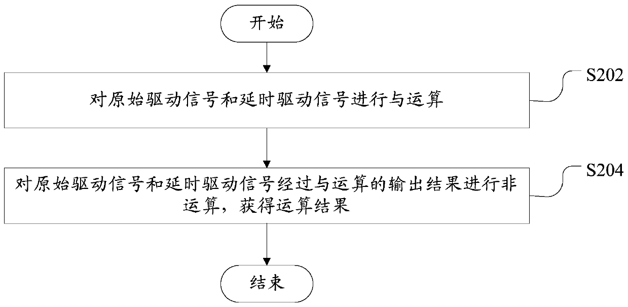
[0055] Such as figure 2 As shown, this embodiment provides a method for removing interference signals in overcurrent protection. In addition to the technical features of the above-mentioned embodiments, this embodiment further includes the following technical features.

[0056] Performing the first calculation on the original driving signal and the delayed driving signal, and obtaining the calculation result specifically includes the following steps:

[0057] Step S202, performing an AND operation on the original driving signal and the delayed driving signal;

[0058] Step S204, performing a negation operation on the output result of the AND operation of the original driving signal and the delayed driving signal to obtain an operation result.

[0059] In this embodiment, and budget means: when the original driving signal and the delayed driving signal are both high level, the output result is high level; when the original driving signal and the delayed driving signal are not...


PUM


Abstract

The invention relates to a method and a system for removing interference signals in overcurrent protection. The method for removing the interference signal in overcurrent protection comprises the following steps of comparing a current sampling signal with a current protection threshold to obtain a comparison result; performing delay processing of the original driving signal to obtain a delay driving signal; performing first operation of the original driving signal and the delay driving signal to obtain an operation result; and performing second operation of the comparison result and the operation result to obtain an over-current protection result without the interference signal. The method is advantaged int hat the interference signal in overcurrent protection can be removed to avoid unnecessary overcurrent protection on electrical equipment, so working efficiency and the operation stability degree of the electrical equipment are improved.

Description

technical field [0001] The invention relates to the technical field of current overload protection, in particular to a method and system for removing interference signals in overcurrent protection. Background technique [0002] In electrical equipment, in order to realize the protection of circuits or electronic components, it is necessary to sample the current flowing through the circuit, and judge whether it is necessary to perform overcurrent protection on electrical equipment according to the size of the sampled current. [0003] One of the shortcomings in the related technology is that when the electric drive controller is sampling the current, it will cause interference on the sampling signal due to the switching of the driving high and low levels. The current acquisition value has interference, so it is easy to misjudge when judging. Therefore, when the electric drive controller performs current sampling, it will interfere with the sampling signal of the current samp...

Claims


Application Information

Patent Timeline
Patent Type & Authority Applications(China)
IPC IPC(8): H02H3/05H02H3/08H02H1/00G01R19/165
CPCH02H3/05H02H3/08H02H1/0007G01R19/165
Inventor 刘超姚洪涛胡勇鹏
Owner HUNAN SANY INTELLIGENT CONTROL EQUIP
Why Eureka
Try Eureka