Direct-current transmission line protection method based on initial voltage traveling wave frequency domain attenuation rate

A DC transmission line, initial voltage technology, applied in the direction of emergency protection circuit devices, electrical components, etc., can solve the problems of reduced protection sensitivity, inability to accurately identify high-resistance faults, etc., and achieve the effect of high sensitivity

Active Publication Date: 2020-07-28
SHANDONG UNIV
View PDF7 Cites 4 Cited by
  • Summary
  • Abstract
  • Description
  • Claims
  • Application Information

AI Technical Summary

Problems solved by technology

The above methods operate quickly, but there is a problem that the protection sensitivity decreases significantly with the increase of the transition resistance, and the high-resistance fault in the area cannot be accurately identified.

Method used


Image

  • Direct-current transmission line protection method based on initial voltage traveling wave frequency domain attenuation rate
  • Direct-current transmission line protection method based on initial voltage traveling wave frequency domain attenuation rate
  • Direct-current transmission line protection method based on initial voltage traveling wave frequency domain attenuation rate

Examples


Embodiment 1

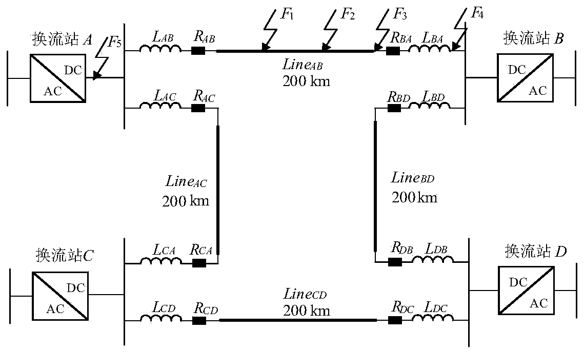
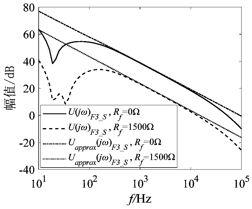
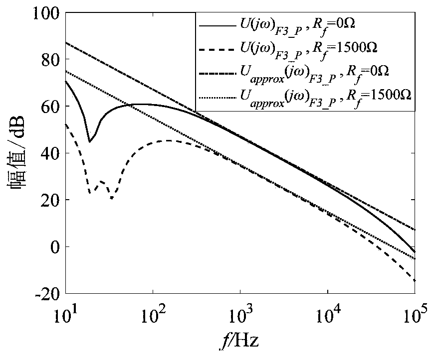
[0034] The present invention is based on the analysis of the frequency domain attenuation rate of the initial voltage of the fault and concludes that when the following conditions are met: the current-limiting reactor is not less than 50mH, the transition resistance of the internal fault is less than 1500Ω, and the transition resistance of the external unipolar fault is less than 325Ω , The transition resistance of the bipolar fault outside the area is less than 650Ω, and the distance to the fault is less than 800km. Within the frequency band of 1k~10kHz, the attenuation rate of the initial voltage traveling wave with the increase of frequency can be approximately constant. The frequency domain attenuation rate of the initial voltage traveling wave under an external fault is twice that of an internal fault.

[0035] figure 1 It is a schematic diagram of ±400kV flexible DC transmission system. figure 1 Middle L ij (i, j = A, B, C, D) are current-limiting reactors, all of which are...

Embodiment 2

[0079] The purpose of this embodiment is to provide a computing device, including a memory, a processor, and a computer program stored on the memory and running on the processor, and the processor implements the specific steps in the first embodiment when the program is executed. .

Embodiment 3

[0081] The purpose of this embodiment is to provide a computer-readable storage medium.

[0082] A computer-readable storage medium on which a computer program is stored, and when the program is executed by a processor, the specific steps in the first embodiment are executed.


PUM


Abstract

The invention discloses a direct-current transmission line protection method based on initial voltage traveling wave frequency domain attenuation rate. The method is characterized by comprising the following steps of: measuring voltages at head end protection installation positions of a positive electrode and a negative electrode of a direct-current line, and constructing a low-voltage starting criterion; if protection is started, measuring the currents at the head end protection installation positions of the positive electrode and the negative electrode of the direct-current line, and identifying a fault direction according to the symbols of the current fault component integral value of the positive electrode or the negative electrode; if the fault is a forward fault, calculating the line-mode voltage traveling wave of the direct current line, performing stationary wavelet transform of different scales on the line-mode voltage traveling wave, and extracting a wavelet transform modulusmaximum value under the corresponding scale; and calculating the equivalent attenuation rate in the initial voltage traveling wave frequency domain, and identifying the faults inside and outside theline area according to the absolute value of the rate. According to the method, the requirement for rapid main protection of the direct-current line is met, and the internal high-resistance fault andthe external fault can be reliably recognized with high sensitivity.

Description

Technical field [0001] The invention belongs to the field of power system relay protection, and in particular relates to a DC transmission line protection method based on an initial voltage traveling wave frequency domain attenuation rate. Background technique [0002] The statements in this section merely provide background information related to the present disclosure, and do not necessarily constitute prior art. [0003] DC transmission has significant technical advantages in large-scale renewable energy grid connection, non-synchronous AC system connection and long-distance large-capacity transmission, and its application will become more and more extensive. Due to the low inertia characteristics of the DC grid, a DC fault will generate a large short-circuit current in a very short time, which will cause great damage to the semiconductor devices in the converter station, and even cause the converter station to lock up and the entire network to collapse. Zhangbei DC power grid ...

Claims


Application Information

Patent Timeline
Patent Type & Authority Applications(China)
IPC IPC(8): H02H7/26
CPCH02H7/265H02H7/268
Inventor 丛伟张韵琦
Owner SHANDONG UNIV
Why Eureka
Try Eureka