Automatic coil winding system for motor production

An automatic winding and coil technology, which is applied in the direction of electric components, manufacturing motor generators, electrical components, etc., can solve the problems of affecting the winding quality and production efficiency of the motor, affecting the winding of the motor coil, and the confusion of coil winding and unwinding.

Active Publication Date: 2020-07-28
LUAN QIANGLI MOTOR CO LTD
View PDF20 Cites 1 Cited by
  • Summary
  • Abstract
  • Description
  • Claims
  • Application Information

AI Technical Summary

Problems solved by technology

[0002] At present, in the manufacturing process of the motor, the winding of the motor coil is the most important link. The quality of the winding quality of the motor coil and the winding efficiency of the motor coil directly affect the quality of the motor and the production efficiency of the motor. The winding of the coil adopts manual winding, and its wind

Method used


Image

  • Automatic coil winding system for motor production
  • Automatic coil winding system for motor production
  • Automatic coil winding system for motor production

Examples


Embodiment 1

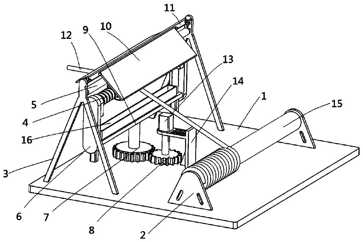
[0029] see Figure 1-5 , an automatic coil winding system for motor production, including a base plate 1, a winding drive mechanism installed on the base plate 1, a winding guide mechanism and a pressing mechanism, and the winding guide mechanism includes a rotating coil mounted on the top surface of the base plate 1 The turntable 7, the power mechanism for driving the turntable 7 to rotate, the horizontal plate 9 above the turntable 7, the side plates 6 fixed at the two ends of the two horizontal plates 9, the guides fixed between the two side plates 6 The rod 4 and the guide plate 17 that is movably sleeved with the guide rod 4.

[0030] Wherein, the top of the rotating disk 7 is connected to the horizontal plate 9 by a longitudinal rotating shaft, the annular inner wall of the guide disc 17 is provided with an internal thread, the outer wall of the guide rod 4 is provided with an external thread, the guide disc 17 is spirally connected with the guide rod 4, and the guide di...

Embodiment 2

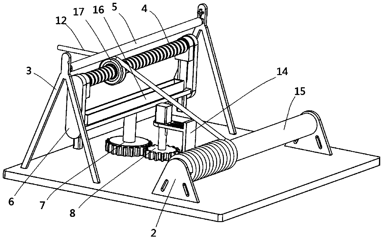
[0039] In this example, see figure 1 , Image 6 , on the basis of Embodiment 1, a moving seat 27 is longitudinally slidably connected to the inner sides of the two side plates 6, and the two ends of the guide rod 4 are respectively fixed on the two moving seats, and the bottoms of the two ends of the horizontal plate 9 Drivers 28 are installed, and the telescopic ends of the drivers 28 are used to drive the moving seat 27 to move longitudinally;

[0040]Also be fixed with the push rod 11 that is positioned at the top of pressure rod 5 between the top of two brackets 3, the opposite both sides of push rod 11 all are connected with baffle plate 10 by pin shaft rotation, the movable end of baffle plate 10 is used for The winding wires 12 on both sides of the guide disk 17 are pressed down, thereby increasing the contact area between the winding wire 12 and the wire groove 24 on the guide disk 17 and increasing the frictional force.

[0041] When the present invention is in use,...


PUM


Abstract

The invention discloses an automatic coil winding system for motor production. The winding device comprises a bottom plate, and a winding driving mechanism, a winding guide mechanism and a pressing mechanism which are mounted on the bottom plate, the winding guide mechanism comprises a rotary disc rotationally arranged on the top face of the bottom plate, a power mechanism driving the rotary discto rotate, transverse plates arranged above the rotary disc, side plates fixed to the two ends of the two transverse plates, a guide rod which is fixed between the two side plates and a guide disc which is movably sleeved with the guide rod; the upper part of the rotary disc is connected to the transverse plates through a longitudinal rotating shaft; internal threads are formed in the annular inner wall of the guide disc, external threads are formed in the outer wall of the guide rod, the guide disc is spirally connected with the guide rod, a wire groove of the guide disc is used for conveyingwound wires, the pressing mechanism is used for extruding the wound wires to make contact with the wire groove, and the winding driving mechanism is used for driving the wound wires to be conveyed. Winding is convenient, the winding can be wound on the rotor in order, and the working efficiency is improved.

Description

technical field [0001] The invention relates to the field of motor production, in particular to an automatic coil winding system for motor production. Background technique [0002] At present, in the manufacturing process of the motor, the winding of the motor coil is the most important link. The quality of the winding quality of the motor coil and the winding efficiency of the motor coil directly affect the quality of the motor and the production efficiency of the motor. The winding of the coil adopts manual winding, and its winding efficiency is low. During the winding process of the motor coil using the motor coil winding machine, when the movement of each component is inconsistent, there will be confusion in the winding and unwinding of the coil, which will affect the The winding of the motor coil is affected, which affects the winding quality and production efficiency of the motor. Contents of the invention [0003] The object of the present invention is to provide a...

Claims


Application Information

Patent Timeline
IPC IPC(8): H02K15/08
CPCH02K15/08
Inventor 赵贤福杨兆阳刘翀刘月明孙平
Owner LUAN QIANGLI MOTOR CO LTD
Why Eureka
Try Eureka