Staggered bonding metal circuit

A metal circuit and interleaving technology, which is applied in the direction of printed circuit, printed circuit manufacturing, printed circuit assembly of electric components, etc., can solve problems such as abnormal operation, large use limitations, and reduced product area, so as to save bonding space, The effect of simple modification and strong operability

Inactive Publication Date: 2020-07-28
ANHUI FANGXING PHOTOELECTRIC NEW MATERIALS TECH
View PDF7 Cites 0 Cited by
  • Summary
  • Abstract
  • Description
  • Claims
  • Application Information

AI Technical Summary

Problems solved by technology

[0003] With the gradual increase in the wiring space requirements of electronic products today, when the number of channels is increasing and the bonding space is getting smaller and smaller, the conventional channel design in the bonding area cannot work normally under the limitation of certain structural spaces. , the use is limited, and it is not conducive to reducing the area of ​​the product

Method used


Image

  • Staggered bonding metal circuit
  • Staggered bonding metal circuit
  • Staggered bonding metal circuit

Examples


Embodiment 1

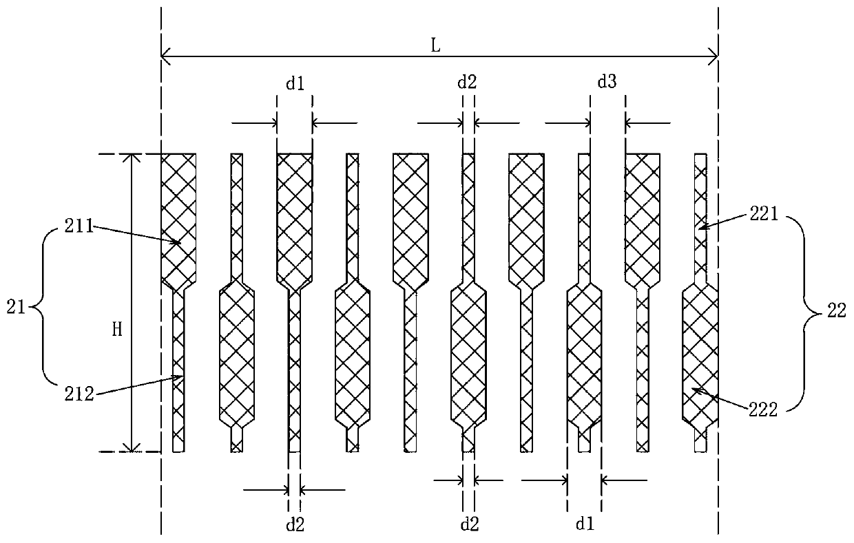
[0036] Embodiment 1: as the description attached figure 2 As shown, the first wide channel 211 and the second wide channel 222 are staggered, the first narrow channel 212 and the second narrow channel 221 are staggered, the line widths of the first wide channel 211 and the second wide channel 222 are equal, and the first wide channel 211 and the second wide channel 222 have the same line width. The line width of a narrow channel 212 and the second narrow channel 221 is equal, the first wide channel 211 and the second wide channel 222 are a single rectangle, the first narrow channel 212 and the second narrow channel 221 are strips, and the first narrow channel 212 The connection is arranged at the bottom of the first wide channel 211 and the connection is provided with a bevel transition, the second wide channel 222 is connected at the non-end point of the second narrow channel 221 and the connection is provided with a bevel transition, the first narrow channel The 212 connect...

Embodiment 2

[0037] Embodiment two: as the description attached image 3 As shown, the first wide channel 211 and the second wide channel 222 are staggered, the first narrow channel 212 and the second narrow channel 221 are staggered, the line widths of the first wide channel 211 and the second wide channel 222 are equal, and the first wide channel 211 and the second wide channel 222 have the same line width. The line width of a narrow channel 212 and the second narrow channel 221 is equal, the first wide channel 211 and the second wide channel 222 are a single rectangle, the first narrow channel 212 and the second narrow channel 221 are strips, and the first narrow channel 212 The connection is set at the leftmost end of the first wide channel 211 and the connection is provided with a bevel transition, and the second narrow channel 221 is connected at the rightmost end of the second wide channel 222 and the connection is provided with a bevel transition. Similarly, according to the metal ...

Embodiment 3

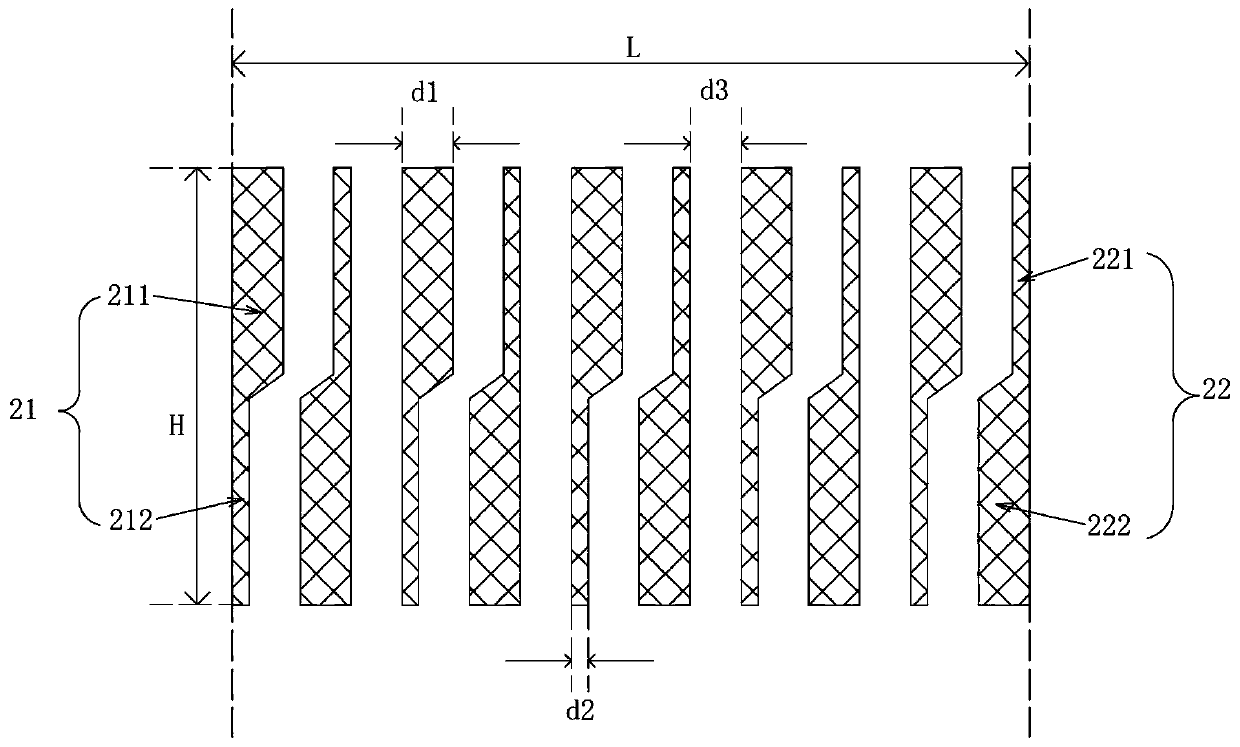
[0038] Embodiment three: as the description attached Figure 4 As shown, the first wide channel 211 and the second wide channel 222 are staggered, the first narrow channel 212 and the second narrow channel 221 are staggered, the line widths of the first wide channel 211 and the second wide channel 222 are equal, and the first wide channel 211 and the second wide channel 222 have the same line width. The line width of a narrow channel 212 and the second narrow channel 221 is equal, the first wide channel 211 and the second wide channel 222 are a plurality of squares, the first narrow channel 212 and the second narrow channel 221 are strips, and the first narrow channel The 212 connection is set at the middle position of the first wide channel 211, and the second narrow channel 221 is connected at the middle position of the second wide channel 222. Similarly, based on the calculation of 10 metal lines, the line width d1 of the wide channel is set as 0.3mm, the line width d2 of t...


PUM


Abstract

The invention discloses a staggered bonding metal circuit. The staggered bonding metal circuit comprises a first metal circuit and a second metal circuit, wherein the first metal circuit comprises first wide channels and first narrow channels, the second metal circuit comprises second narrow channels and second wide channels, the first wide channels and the second wide channels are arranged in a staggered mode, and the first narrow channels and the second narrow channels are arranged in a staggered mode. According to the staggered bonding metal circuit provided by the invention, an original arrangement design is changed, so the wide channels and the narrow channels are sequentially arranged at intervals in a horizontal direction, bonding space can be effectively saved, operability is high,and the staggered bonding metal circuit is very worthy of popularization.

Description

technical field [0001] The invention relates to the technical field of metal circuits, in particular to an interleaved bonding metal circuit. Background technique [0002] Most of the conventional channel design in the bonding area is to set the wide channel for bonding at one end and the narrow channel for connection at the other end. The disadvantage of this is that it takes up a lot of space. [0003] With the gradual increase in the wiring space requirements of electronic products today, when the number of channels is increasing and the bonding space is getting smaller and smaller, the conventional channel design in the bonding area cannot work normally under the limitation of certain structural spaces. , the use is more limited, and it is not conducive to reducing the area of ​​​​the product. Contents of the invention [0004] The purpose of the present invention is to provide an interleaved bonding metal circuit to solve the problems raised in the background art abo...

Claims


Application Information

Patent Timeline
Patent Type & Authority Applications(China)
IPC IPC(8): H05K3/30H05K3/32H05K1/18
CPCH05K1/182H05K3/301H05K3/32
Inventor 郑琦林刘月豹晏竹冰张阳廖晓芮叶飞
Owner ANHUI FANGXING PHOTOELECTRIC NEW MATERIALS TECH
Why Eureka
Try Eureka