
Ioniser equipped with an ion-flux accelerator in particular for protection against mosquitoes

An ion and equipment technology, applied in the field of ion generators, can solve problems such as incompatibility and increased power consumption of ion generators

Inactive Publication Date: 2020-07-28
ANCILIA PROTECT LTD
View PDF4 Cites 0 Cited by
  • Summary
  • Abstract
  • Description
  • Claims
  • Application Information

AI Technical Summary

Problems solved by technology

However, this results in increased electrical consumption of the ionizer and is not compatible with prolonged use especially when traveling or in areas without mains power

Method used


Image

  • Ioniser equipped with an ion-flux accelerator in particular for protection against mosquitoes
  • Ioniser equipped with an ion-flux accelerator in particular for protection against mosquitoes
  • Ioniser equipped with an ion-flux accelerator in particular for protection against mosquitoes

Examples


Embodiment Construction

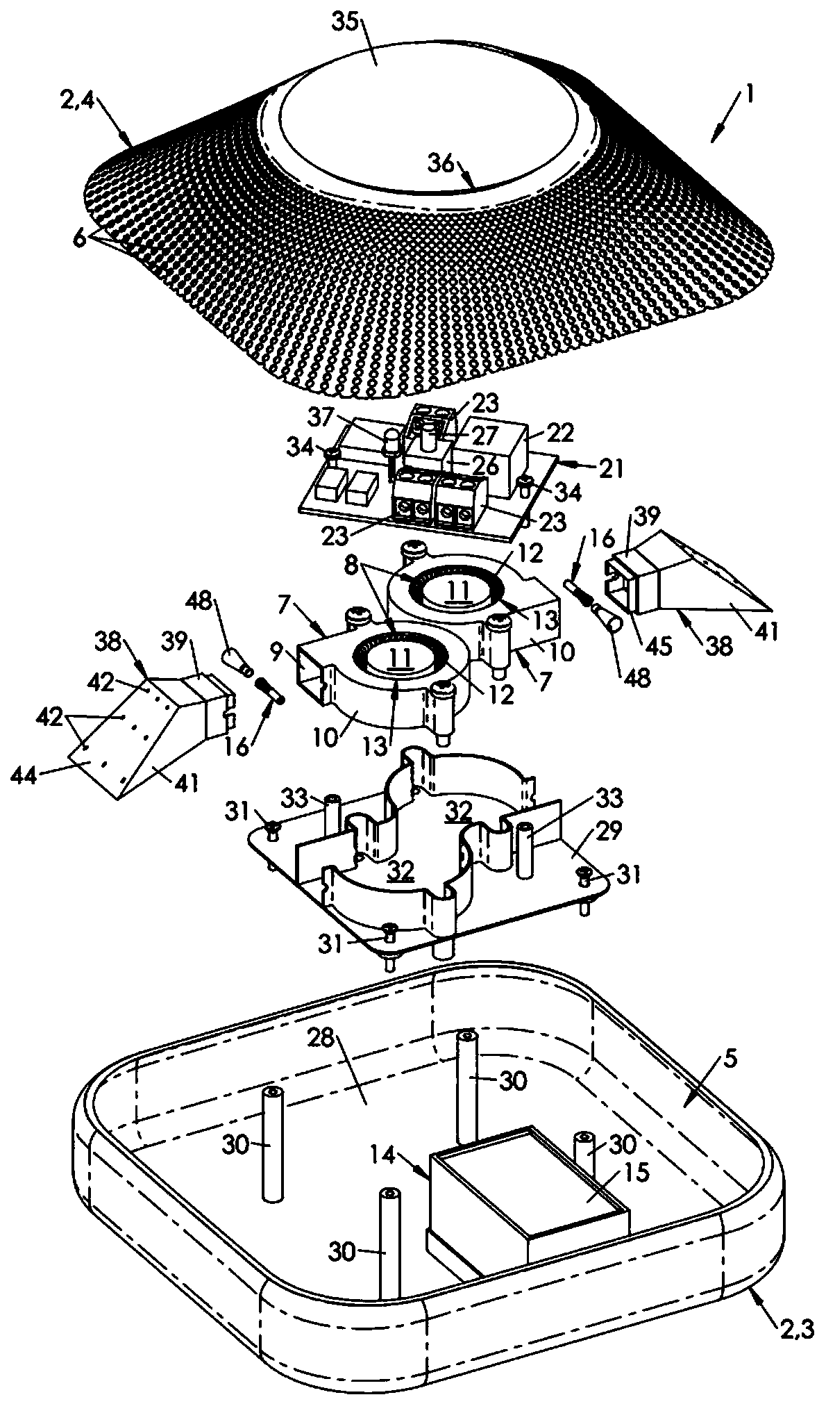
[0038] in figure 1 In the figure, an air ionization device is shown, hereinafter referred to as ion generator 1 for short. The ion generator 1 is designed to generate one or more pulsed ion streams, intended to unite with particles suspended in air with opposite charges.

[0039] The molecules (or molecular groups) formed by the combination of pulsed ions and particles are heavy and stick to the ground under the action of their weight.

[0040] The ion generator 1 is advantageously designed to generate negative ions (anions), usually CO3 ions. In the following, how to achieve this will be shown.

[0041] The ion generator 1 first includes a housing 2.

[0042] In the example shown, the housing 2 includes a base 3 and a cover 4.

[0043] The base 3 may be placed on a support (for example, a table) to be fixed to a wall or partition (surface mounting), or it may be fixed to a ceiling (ceiling mounting).

[0044] In the example shown, the base 3 has substantially square edges (preferably ...


PUM


Abstract

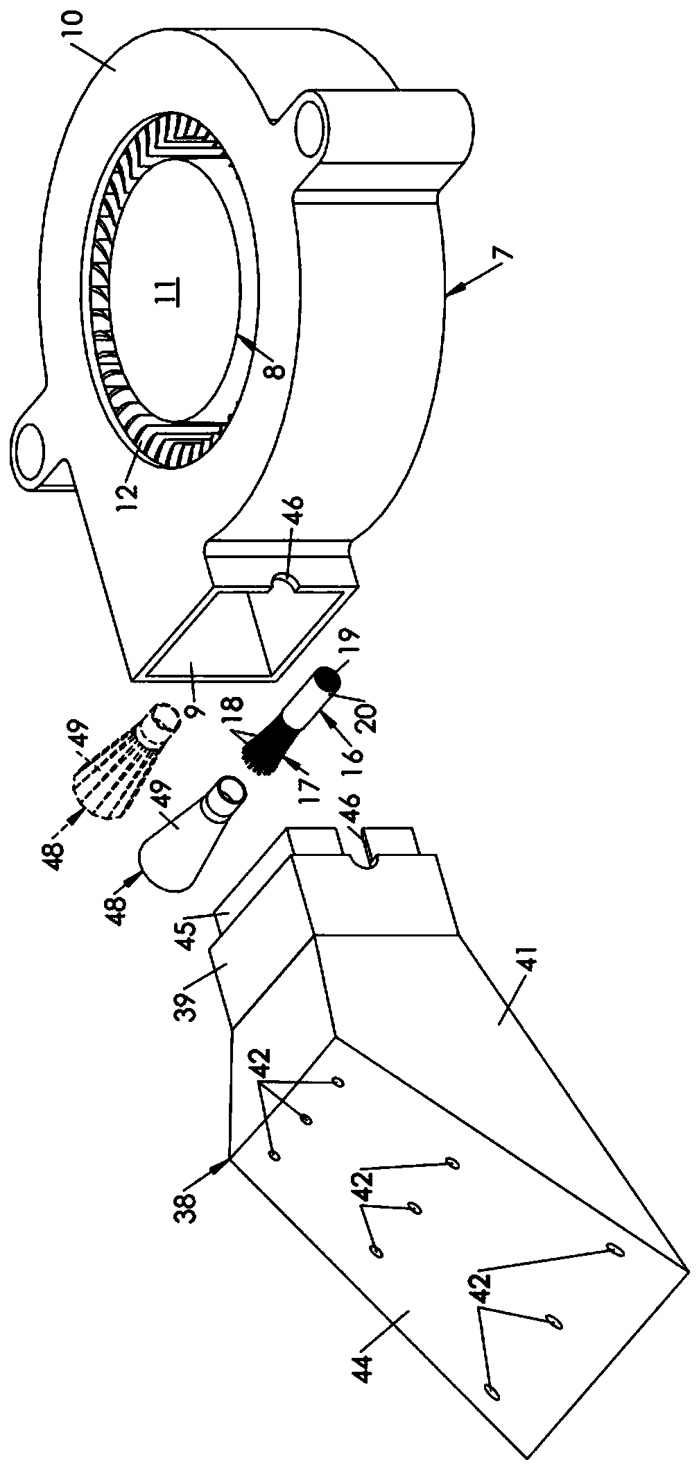
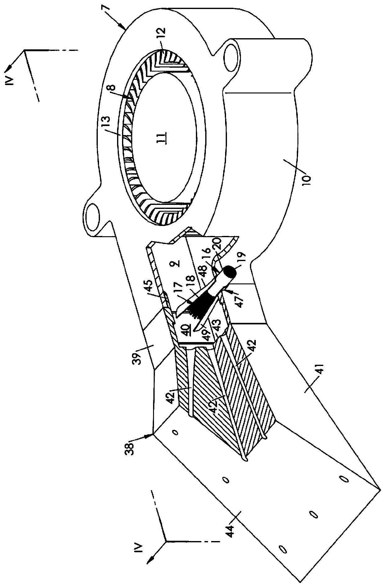
An air ionisation device (1) which comprises, in a casing (2): a blower (7), which comprises a rotor (8) for generating a drawn air flow and an exhaust duct (9) for channelling this flow; a device (14) for producing ions, which comprises: a high-voltage electrical generator (15); an electrode (16) connected to the generator (15), a free end of which, formed from a bundle of filaments of conductivematerial, extends in a line with the exhaust duct (9) in order to release the ions by the corona effect; a diffuser (38) provided with: a tube (39) which defines a compression chamber in the extension of the exhaust duct (9), a divergent nozzle (41) which extends the tube (39) and comprises a series of channels (42) which extend from an inner face of the divergent nozzle (41) to an opposing outerface (44).

Description

Technical field [0001] The invention relates to the field of ion generators. Background technique [0002] Ionizers are usually used to purify the air. The principle is very simple. It is based on corona discharge: one (or more) electrodes connected to a high-voltage (low-intensity) power source cause ionization of the surrounding environment, accompanied by discharge. [0003] In fact, the electrodes can be formed (at least at one free end) from very thin filaments (for example, made of glass or carbon fiber, considered as electrical conductors). These filaments are placed in the air flow generated by the blower, and the air flow takes away the ions. [0004] Ions couple with particles suspended in the air, and by becoming heavier, they help stick to the ground. [0005] A typical ion generator using this technology is described in US Patent No. 5,268,009. [0006] It has recently been discovered that ionizers can help repel insects (especially Diptera) that are usually attracted by...

Claims


Application Information

Patent Timeline
IPC IPC(8): A61L9/22H01T19/00F24F7/00H01T23/00
CPCA61L9/22H01T19/00H01T23/00F24F8/192F24F8/30Y02A50/20F24F7/00A61L2209/16A61L2209/134A61L2209/11B03C3/38A01M29/28
Inventor P.诺顿C.乔万内蒂S.E.拉曼里
Owner ANCILIA PROTECT LTD
Learn More