Hole site correction method applied to automatic drilling and riveting of curved surface products

A technology of automatic drilling and riveting and curved surface, which can be used in ground installations, program-controlled manipulators, manipulators, etc., and can solve problems such as hole position errors.

Active Publication Date: 2020-07-31
JITRI INST OF PRECISION MFG
View PDF5 Cites 8 Cited by
  • Summary
  • Abstract
  • Description
  • Claims
  • Application Information

AI Technical Summary

Problems solved by technology

However, the shape of the aircraft panel is various, and the error of the hole position is related to the curvature of the panel, so the above methods have certain limitations.

Method used


Image

  • Hole site correction method applied to automatic drilling and riveting of curved surface products
  • Hole site correction method applied to automatic drilling and riveting of curved surface products
  • Hole site correction method applied to automatic drilling and riveting of curved surface products

Examples


Embodiment Construction

[0072] Embodiments of the present invention will be described in further detail below in conjunction with the accompanying drawings.

[0073] A hole position correction method applied to automatic drilling and riveting of curved surface products according to the present invention comprises the following steps:

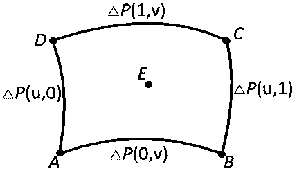
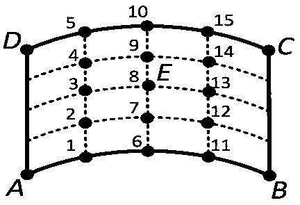
[0074] S1: Set a number of holes to be processed in the hole-making area, and set four reference holes at the four corners of the hole-making area. The theoretical position, normal direction and actual position of the reference holes are known. First, the theoretical positions and Comparing the actual positions to obtain the vector errors of the four reference holes, combining the vector error and the normal fitting bilinear mixed Coons error surface, constructing the error surface function △P(u,v), the information of the four reference holes cannot be obtained during fitting Determine the modulus length of the tangent vector and set it as an unknown number;

[0075] ...


PUM


Abstract

The invention discloses a hole site correction method applied to automatic drilling and riveting of curved surface products. The hole site correction method comprises the following steps that S1, thetheoretical positions and the actual positions of four reference holes are compared to obtain vector errors of the four reference holes, and an error curved surface function is constructed by combining the vector errors and a normal fitting bilinear hybrid Coons error curved surface; S2, the fifth reference hole is introduced into a hole making area, and the error which should be compensated by the reference hole is obtained through substitution; S3, a multi-objective optimization genetic model is established by combining the actual vector errors of the reference hole, and the optimal value ofthe tangent vector model length of the four reference holes is calculated within a certain range, so that the error curved surface function is determined; and S4, the corresponding value is calculated by utilizing the theoretical coordinates of the hole to be machined, then the hole site error of the hole to be machined can be calculated, and finally the error is compensated to the theoretical coordinates to obtain new theoretical coordinates, namely the hole site correction process is completed. The hole site correction method has the advantages of being good in correction effect, wide in application range and capable of meeting the hole making position precision requirement.

Description

technical field [0001] The invention belongs to the field of automatic drilling and riveting error correction of robots, and in particular relates to a hole position correction method applied to automatic drilling and riveting of curved surface products, which is used to correct the error between the processing hole point position and the actual processing hole point position on the process digital model. Background technique [0002] The use of robotic automatic drilling and riveting systems for aircraft assembly can effectively improve the quality and efficiency of aircraft assembly, and has been widely used in the field of aviation manufacturing. The off-line programming system is a prerequisite for automatic drilling and riveting systems of robots. The offline programming system extracts feature information from the process digital model and plans processing tasks, and finally outputs a set of NC programs that can be directly used for processing after simulation optimiza...

Claims


Application Information

Patent Timeline
Patent Type & Authority Applications(China)
IPC IPC(8): B25J9/16B25J11/00B64F5/10
CPCB25J9/1607B25J11/0055B25J11/007B64F5/00
Inventor 田威孙新月胡俊山刘少睿晏阳喻强刘霖
Owner JITRI INST OF PRECISION MFG
Why Eureka
Try Eureka