

Sealing ring edge cutting equipment
A sealing ring and trimming technology, which is applied in metal processing and other directions, can solve the problems of high cost of use and inconsistent thickness of sealing rings
- Summary
- Abstract
- Description
- Claims
- Application Information
AI Technical Summary
Problems solved by technology
Method used
Image

Examples
Embodiment 1
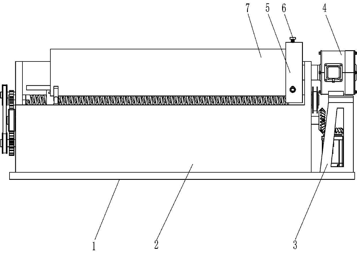
[0021] See Figure 1-Figure 4 , A sealing ring trimming device, including a bottom plate 1, a mounting frame 2, a support frame 3, a first motor 4, an annular placement frame 5, a fastening bolt 6, a drive assembly 8 and a trimming assembly 9, installed on the top of the bottom plate 1. There is a mounting frame 2, a drive assembly 8 is provided between the upper rear side of the mounting frame 2 and the top right side of the bottom plate 1, and an edge trimming assembly 9 is provided on the upper rear side of the mounting frame 2. The trimming assembly 9 is in contact with the drive assembly 8. The support frame 3 is fixedly connected to the top right side of the bottom plate 1 and the first motor 4 is installed on the outer top of the support frame 3 by bolt connection. The output shaft of the first motor 4 penetrates the upper right side of the mounting frame 2 and is connected by a coupling An annular placement frame 5 is provided with fastening bolts 6 evenly spaced in the ...
Embodiment 2
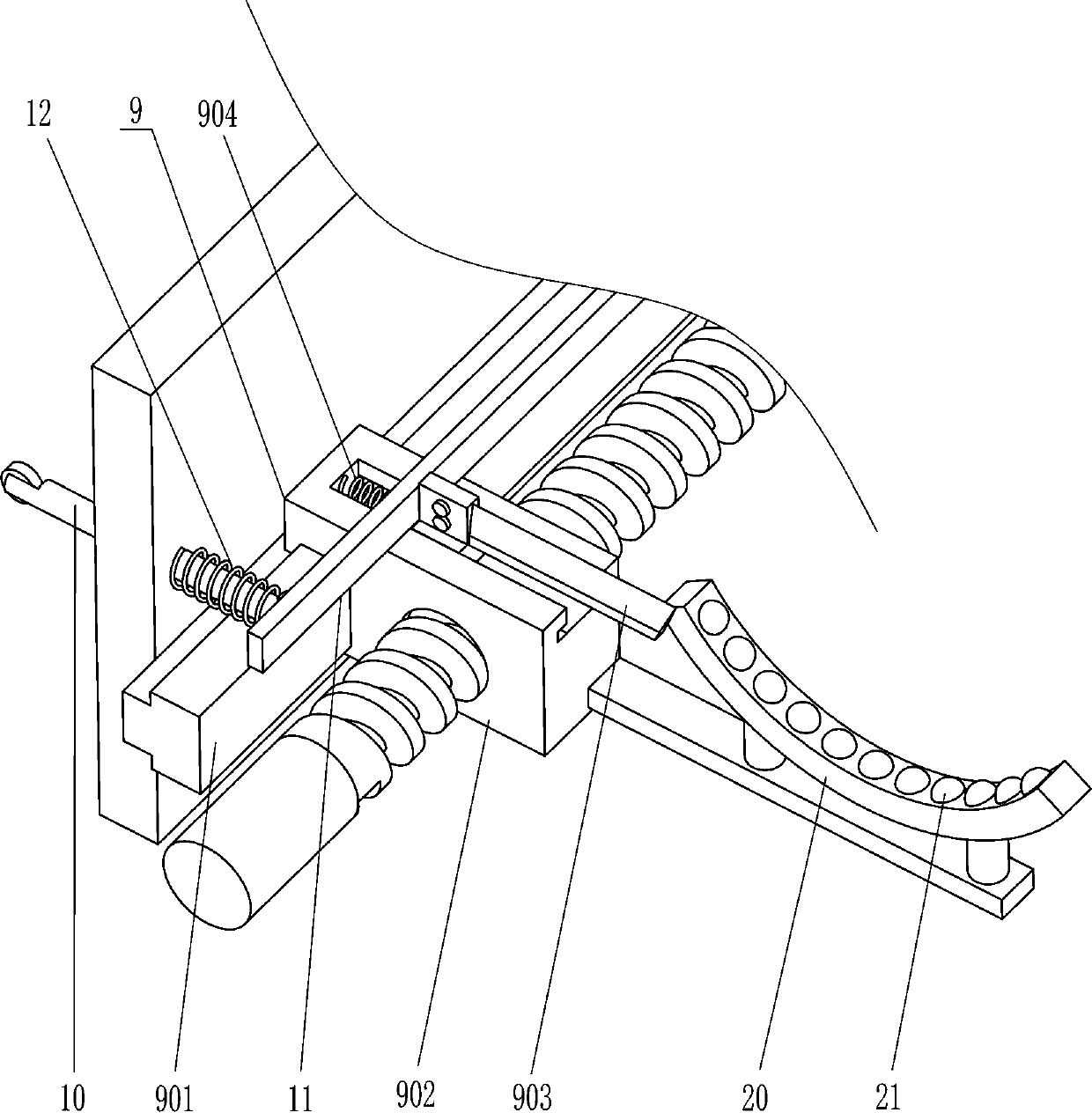
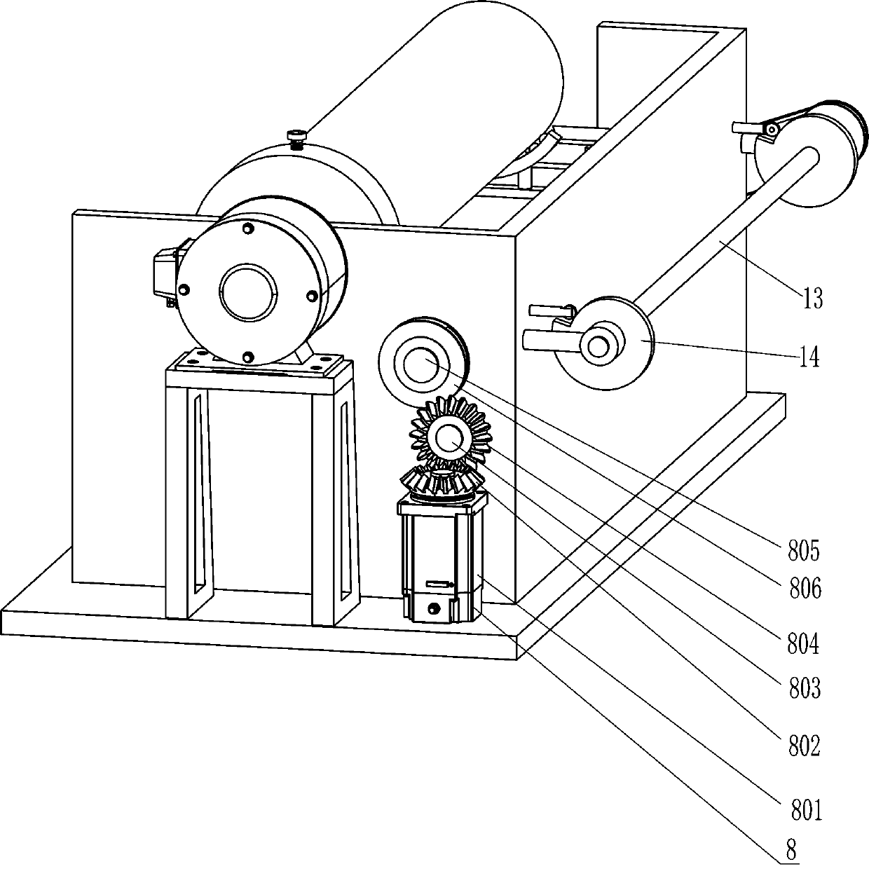
[0028] See Figure 2-Figure 4 Compared with the first embodiment, the main difference of this embodiment is that in this embodiment, it also includes a contact rod 10, a push rod 11, a second spring 12, a second shaft 13, a cam 14, a second transmission wheel 15, and a third The rotating shaft 16, the third transmission wheel 17, the second gear 18 and the third belt 19, the upper part of the rear side of the mounting frame 2 symmetrically slides through the contact rod 10, and the front ends of the contact rods 10 are fixedly connected between the left and right sides. Push rod 11, the front side of the push rod 11 is in contact with the rear end of the cutter 903, the second spring 12 is connected between the left and right sides of the rear side of the push rod 11 and the upper part of the inner and rear side of the mounting frame 2, and the second spring 12 is sleeved in contact On the rod 10, a second rotating shaft 13 is rotatably connected to the upper part of the outer ...
PUM
 Abstract
Description
Claims
Application Information