
Automatic temperature regulation and insulation house

A housing and automatic technology, applied in the direction of roof, roof covering, building, etc., can solve the problems of poor thermal insulation effect, increase cost, increase construction difficulty, etc., and achieve the effect of better comprehensive performance and good windproof effect.

Active Publication Date: 2021-10-15
东莞金积研环境科技有限公司
View PDF7 Cites 0 Cited by
  • Summary
  • Abstract
  • Description
  • Claims
  • Application Information

AI Technical Summary

Problems solved by technology

The waste heat and exhaust gas in the factory building are discharged outside the factory building through the skylight, so as to improve the indoor air quality and reduce the indoor temperature. However, due to the vast factory area, the exhaust effect is limited, and it is still necessary to install an exhaust fan to increase the exhaust gas and waste heat discharge speed.
Like this, promptly increased the difficulty on the construction, will raise cost, consume energy again.
[0003] In view of the above problems, the inventor Huang Jishu Chinese Invention Patent No. 93107395.2 proposed a multi-functional construction method for corrugated building panels, which can solve the above problems to a certain extent. When it enters, water mist is generated, and the water droplets hang on the back of the building cover (corrugated building board), and there is no water breaker, which makes it easy for water to enter the factory building, which brings inconvenience to users
[0004] In addition, the corrugated building board proposed by Chinese invention patent No. 93107395.2 is open and convective all year round, which is only suitable for spring, summer and autumn, and in special environments such as restaurants when it is hot, air conditioning must be installed
When it is extremely cold, the air convection will lower the indoor temperature and the insulation effect will be poor.

Method used


Image

  • Automatic temperature regulation and insulation house
  • Automatic temperature regulation and insulation house
  • Automatic temperature regulation and insulation house

Examples


Embodiment Construction

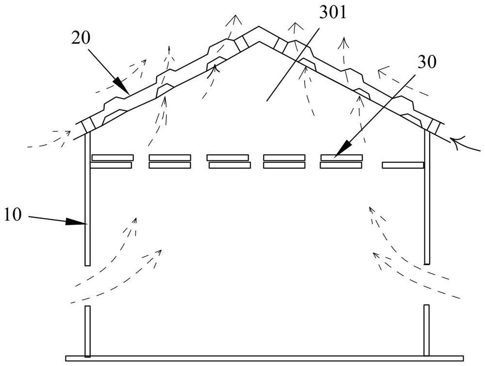
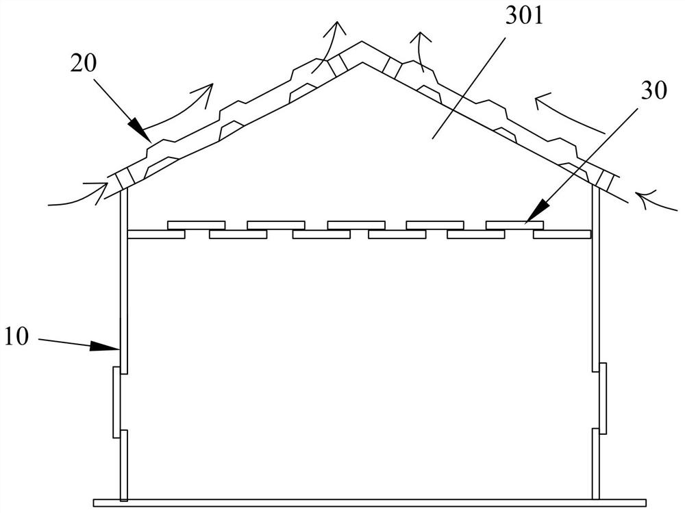
[0051] Please refer to Figure 1 to Figure 8 As shown, it shows the specific structure of the preferred embodiment of the present invention, which is a house with automatic temperature regulation and heat preservation, including an outer wall 10, a roof 20, and a ceiling 30, and multiple outer walls 10 are connected to form an inner space separated from the outside world , the roof 20 is built on the top of the outer wall 10, the ceiling 30 is suspended on the steel frame of the outer wall 10 or the roof 20 and has a certain height between the roof 20, and the temperature-regulated air is formed between the roof 20 and the ceiling 30 Layer 301.

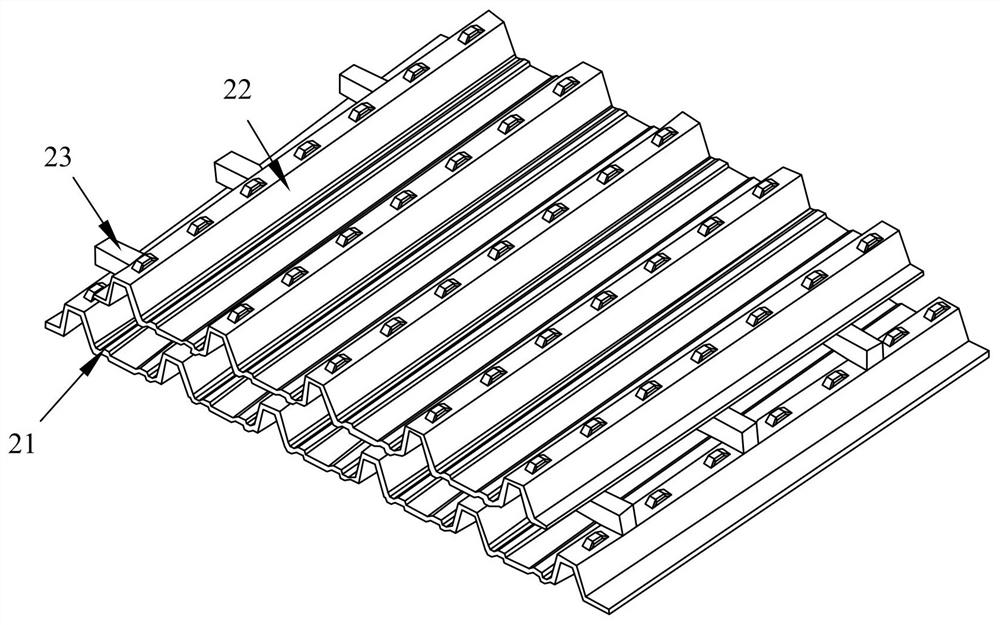
[0052] Wherein, the roof 20 is a waterproof and air-permeable roof, including a lower building cover plate 21 and a superstructure cover plate 22 stacked together, and the lower building cover plate 21 is provided with a plurality of first air convection holes 211. The superstructure cover plate 22 is provided with a plurality of sec...


PUM


Abstract

The invention discloses an automatic temperature-regulating and heat-preserving house, which includes an outer wall, a roof, and a ceiling, and a temperature-regulating air layer is formed between the outer roof and the ceiling. The superstructure cover plate, the lower building cover plate and the superstructure cover plate are all provided with air convection holes; There may be air convection holes, and when the upper ceiling or the lower floor ceiling moves relative to the slide rail, the air convection holes on the ceiling are opened for ventilation or closed for warmth. The roof of the present invention utilizes the principle that the air rises when heated, so that the air naturally generates convection, which can achieve the effects of heat insulation, heat dissipation, heat exhaust, and smoke exhaust. On this basis, the convection holes can be opened and closed in conjunction with the ceiling in spring, autumn and winter Design, and can automatically adjust the temperature and heat preservation, the price is cost-effective.

Description

technical field [0001] The invention relates to the technology in the field of construction, in particular to a house with automatic temperature regulation and heat preservation. Background technique [0002] At present, corrugated building boards are mostly used in temporary buildings or permanent factory buildings. Especially in recent years, more and more corrugated boards are made of various materials, such as the common ones: plastic , galvanized painted steel plate and so on. Due to the reduction of its price, its use is becoming more and more extensive, ranging from small additions to general household buildings to tens of thousands of square meters of factories, stations, and airports, all of which are covered with corrugated building boards. However, its heat insulation effect against the sun is very poor, and most of them are used to prevent wind and rain. If in order to achieve heat insulation, it is necessary to use other heat insulation materials, such as: woo...

Claims


Application Information

Patent Timeline
Patent Type & Authority Patents(China)
IPC IPC(8): E04B1/00E04B9/00E04B9/02E04D13/00
CPCE04B1/00E04B9/001E04B9/02E04D13/00
Inventor 黄颢文黄颢中林美君黄垤树
Owner 东莞金积研环境科技有限公司
Learn More