Building thermal insulation wall

A building insulation and wall technology, applied in the direction of insulation, construction, building components, etc., can solve the problems of increased risk, damage, corrosion and damage of foam insulation layer, etc., to prevent the entry of dust and water vapor, increase service life, increase The effect of thermal insulation

Active Publication Date: 2020-07-31
冠恒建设集团有限公司
View PDF6 Cites 1 Cited by
  • Summary
  • Abstract
  • Description
  • Claims
  • Application Information

AI Technical Summary

Problems solved by technology

But its disadvantage is that since it cannot be installed with heavy things, the decorative layer is relatively light and thin, and it is easily damaged. Once there is a large impact, the decorative layer cannot bear the weight and will be damaged, and then the foam insulation layer is exposed. If it is not repaired in time, the external air, water vapor and dust will continue to enter between the decoration layer and the insulation layer. In the long run, it will easily lead to corrosion and damage of the foam insulation layer, and the connection strength between the decoration layer and the insulation layer will become low and easy to fall off. Reduce the service life and affect the insulation effect of the insulation layer
[0003] In addition, due to the use of the foam insulation layer, its fireproof performance must be improved. Once a fire occurs, the foam insulation layer must be isolated, otherwise the external flame will quickly spread the fire when it contacts the insulation layer, increasing the danger. There are still many deficiencies in fire prevention measures

Method used


Image

  • Building thermal insulation wall
  • Building thermal insulation wall
  • Building thermal insulation wall

Examples


Embodiment Construction

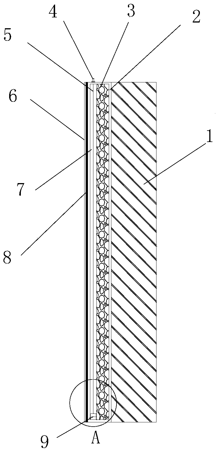
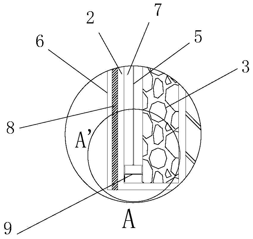
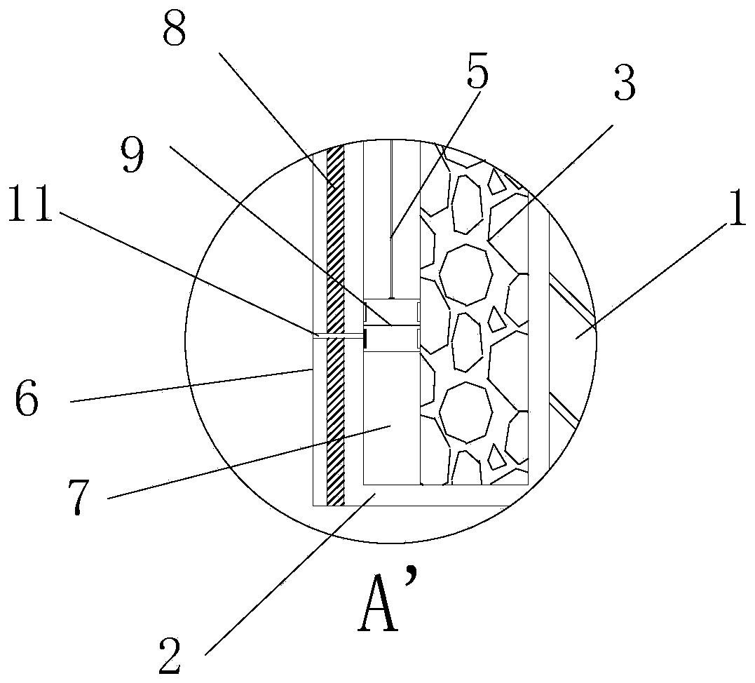
[0019] Such as figure 1 and figure 2 As shown, the thermal insulation wall of this building includes a building concrete matrix 1, and an insulating layer is installed on the outer side of the building concrete matrix 1, and the outer side of the insulating layer is bonded and fixed with a layer of decorative layer 6 through a thin concrete layer 8;

[0020] In this embodiment, the thermal insulation layer includes a thermal insulation shell 2, and a sealed installation cavity is provided inside the thermal insulation shell 2, and a layer of thermal insulation sponge layer 3 is filled in the installation cavity close to the building concrete base 1, and the installation cavity is completed. An air storage chamber 7 is formed behind the heat preservation sponge layer 3, and the air storage chamber 7 is arranged on one side close to the decorative layer 6, and an air charging port 4 is arranged on the top of the heat preservation outer shell 2, and the air storage chamber 7 is ...


PUM


Abstract

The invention discloses a building thermal insulation wall. The building thermal insulation wall comprises a building concrete matrix, a thermal insulation layer is installed on the outer side face ofthe building concrete matrix, and a decorative layer fixedly adheres to the outer side face of the thermal insulation layer through a concrete thin layer. The thermal insulation layer comprises a thermal insulation shell, a sealed mounting cavity is formed in the thermal insulation shell, and the side, close to the building concrete matrix, in the mounting cavity is filled with a thermal insulation sponge layer. An air storage cavity is formed after the thermal insulation sponge layer is installed in the mounting cavity, the air storage cavity is formed in the side close to the decorative layer, and an inflation port is formed in the top of the thermal insulation shell. The building thermal insulation wall has very good sealing capability; and after the outer surface of the wall is damaged, a sealing device can be used for plugging in time to prevent external water vapor and dust from entering the wall, and corrosion to the thermal insulation layer is relieved. In addition, the building thermal insulation wall has very good fireproof capability, and can effectively isolate a fire source.

Description

technical field [0001] The invention relates to the construction field, in particular to a building thermal insulation wall. Background technique [0002] During the construction of the building, in order to improve the insulation and noise performance, a foam insulation layer is usually added to the exterior concrete wall of the building. Because the insulation layer is relatively brittle and light, it is not easy to install heavy tiles on its outer surface, so it is generally just A decorative layer is provided, which can not only solve the aesthetic problem, but also cover the insulation layer. But its disadvantage is that since it cannot be installed with heavy things, the decorative layer is relatively light and thin, and it is easily damaged. Once there is a large impact, the decorative layer cannot bear the weight and will be damaged, and then the foam insulation layer is exposed. If it is not repaired in time, the external air, water vapor and dust will continue to ...

Claims


Application Information

Patent Timeline
Patent Type & Authority Applications(China)
IPC IPC(8): E04B1/76E04B1/94
CPCE04B1/762E04B1/941E04B1/948
Inventor 李丽华
Owner 冠恒建设集团有限公司
Why Eureka
Try Eureka