Electro-hydraulic multi-speed cushion valve capable of being used for near-water medium

A buffer valve, medium technology, applied in the direction of servo motors, servo motor components, fluid pressure actuation system components, etc., can solve the impact of the service life of hydraulic pipeline components, cannot change the flow rate of the hydraulic system circuit, and the valve cannot adjust the flow rate. And other issues

Pending Publication Date: 2020-07-31
郑州恒达智控科技股份有限公司
View PDF0 Cites 2 Cited by
  • Summary
  • Abstract
  • Description
  • Claims
  • Application Information

AI Technical Summary

Problems solved by technology

[0002] Due to the special requirements for safety and stability in coal mining, ordinary valves cannot be used to adjust flow in the underground environment. Hydraulic valves are a type of valve commonly used in underground hydraulic systems. Traditional hydraulic valves cannot be combined with electro-hydraulic. The flow is automatically controlled. Most of the hydraulic control valves can only control the two states of fully open or fully closed, and cannot change the flow in the hydraulic system circuit.
This leads to the fact that in the traditional downhole hydraulic circuit, the actuator cylinder can only maintain the same inflow and outflow flow during the whole process of operation. This control method mainly has the following defects: (1) The starting pressure is very high in the initial stage of the cylinder execution. Even greater than the pressure of the pump station, the flow rate of the driving fluid is large, and it will impact the actuator for a long time, which will easily lead to the failure of the cylinder joint seat and the fracture of the shear pin; The action control of the mechanism is not precise enough; at the same time, the service life of hydraulic pipeline components will also be affected, which is not energy-saving and environmentally friendly, and wastes effective resources

Method used


Image

  • Electro-hydraulic multi-speed cushion valve capable of being used for near-water medium
  • Electro-hydraulic multi-speed cushion valve capable of being used for near-water medium
  • Electro-hydraulic multi-speed cushion valve capable of being used for near-water medium

Examples


Embodiment 1

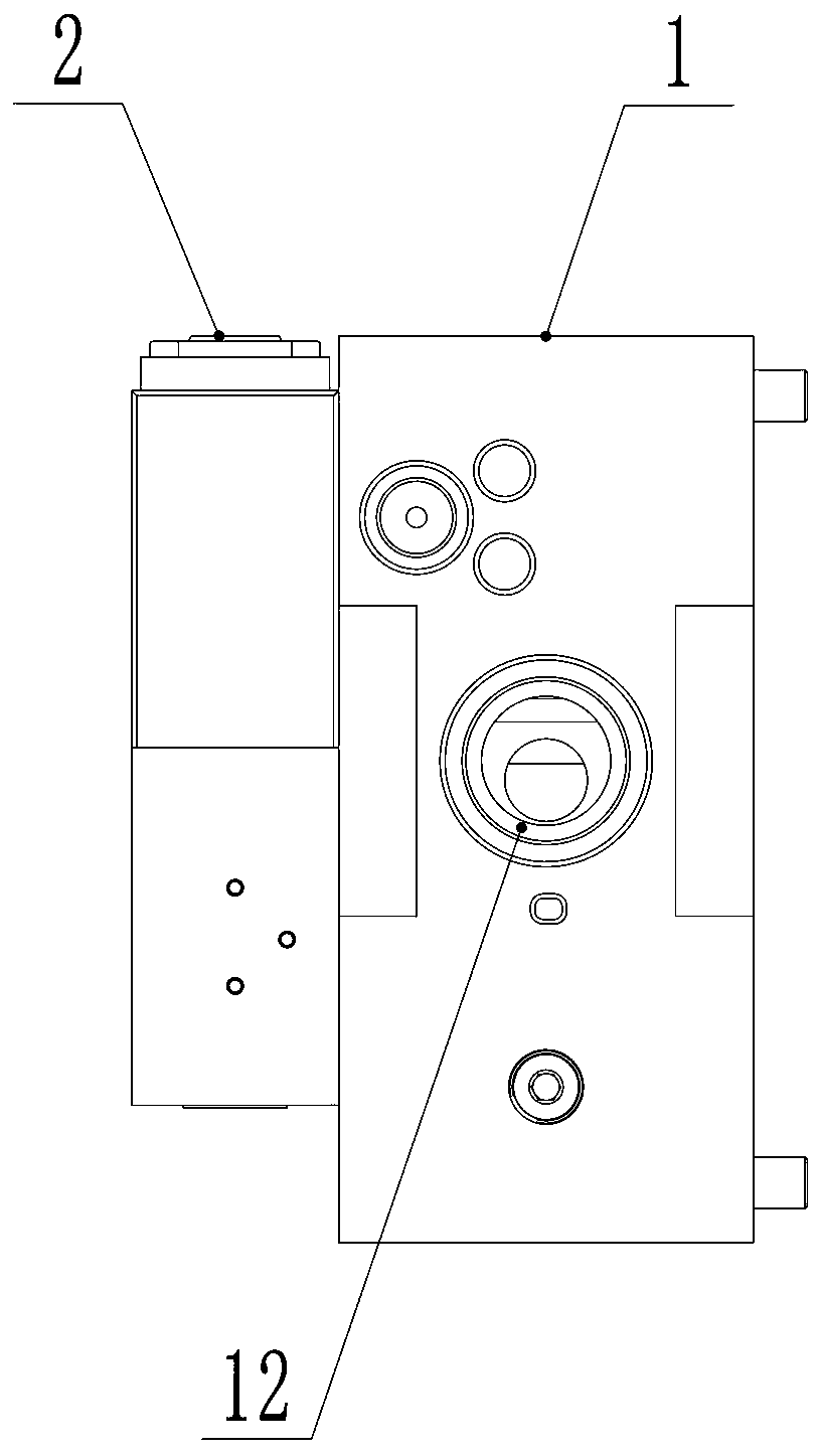
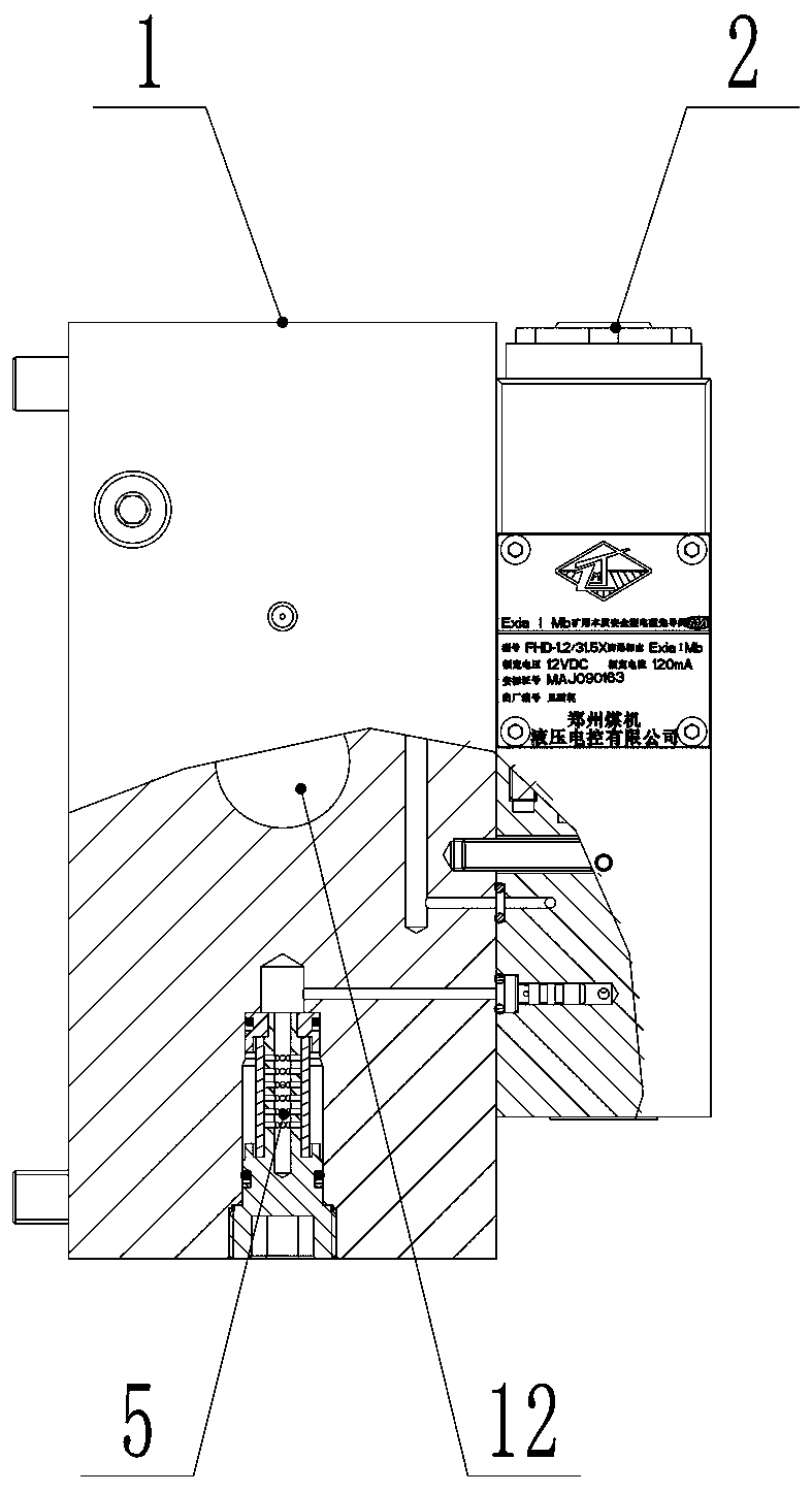
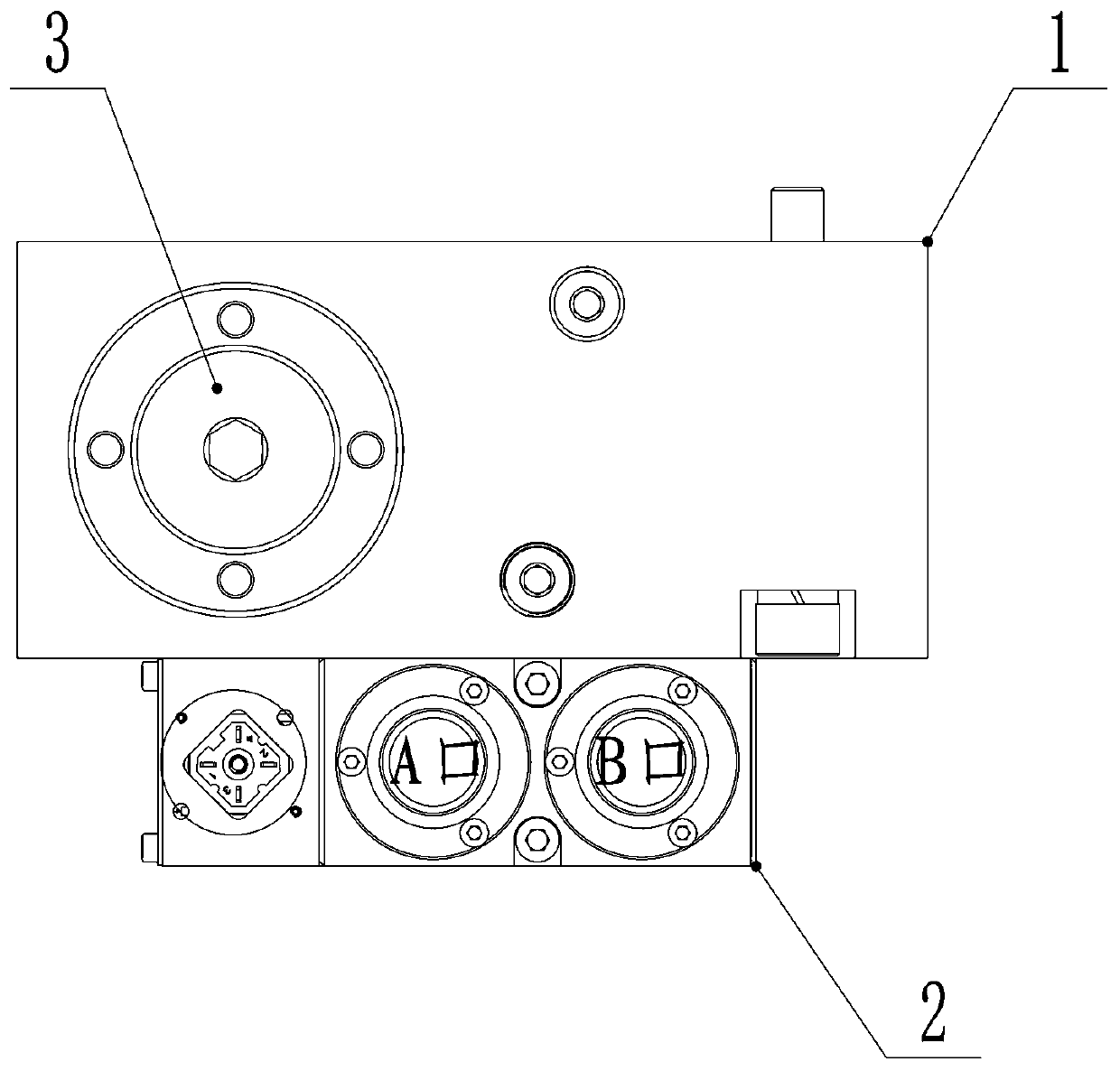
[0024] Such as Figure 1-5 As shown, an electro-hydraulic multi-speed buffer valve that can be used for near-water media includes a main valve body 1, a main channel opened in the main valve body 1, and a main valve body opened in the main valve body 1. The thin flow channel 4 and the electromagnetic pilot valve 3, the main channel includes a liquid inlet flow channel 11, a liquid outlet flow channel 12, and a communication cavity 13 connected between the liquid inlet flow channel 11 and the liquid outlet flow channel 12 , the communication chamber 13 is provided with a shut-off valve assembly, the shut-off valve assembly is a hydraulically controlled one-way valve string 3; The liquid outlet channel 12; the liquid inlet channel 11 is also connected with the control oil inlet of the electromagnetic pilot valve 2, and the first control oil outlet of the electromagnetic pilot valve 2 (ie Figure 4 Port B in the center) is connected to the hydraulic control port of the hydraulic...

Embodiment 2

[0031] Such as Figure 6 As shown, the difference between this embodiment and Embodiment 1 is that a small hydraulic control flow channel 14 is set in the main valve body 1, and a small flow hydraulic control flow channel 14 is set in the hydraulic control small flow channel 14 One-way valve string 15, the two ends of the hydraulically controlled fine flow channel 14 are respectively connected to the liquid inlet flow channel 11 and the liquid outlet flow channel 12, and the second control oil outlet of the electromagnetic pilot valve 2 ( which is Figure 4 Port A in the middle) communicates with the hydraulic control port of the small flow hydraulic control check valve string 15; the electromagnetic pilot valve 2 itself has two control oil outlets ( Figure 4A port and B port in the middle), can control the two hydraulic control components separately, the original hydraulic control check valve string 3 uses port B, and the small flow hydraulic control check valve string 15 c...

Embodiment 3

[0034] Such as Figure 7 As shown, an electro-hydraulic multi-speed control system includes a liquid inlet main pipe 6, a liquid outlet main pipe 7, an electro-hydraulic main control valve 8 and a hydraulic actuator 9, and the liquid inlet main pipe 6 communicates with the electro-hydraulic main control valve 8 The main oil inlet, the liquid outlet main pipe 7 is connected to the main oil outlet of the electro-hydraulic main control valve 8, the electro-hydraulic main control valve 8 controls the execution action of the hydraulic actuator 9, and the hydraulic actuator 9 Specifically, it can be a jack, a hydraulic support column, an oil cylinder, etc. The above-mentioned equipment is a commonly used control circuit in the existing downhole hydraulic system, and no creative labor is required to obtain it.

[0035] In order to improve the control accuracy and durability of the hydraulic actuator 9, the electro-hydraulic multi-speed buffer valve 10 in the aforementioned embodimen...


PUM


Abstract

The invention provides an electro-hydraulic multi-speed cushion valve capable of being used for near-water media. The electro-hydraulic multi-speed cushion valve comprises a main valve body, a main runner arranged in the main valve body, a thin runner arranged in the main valve body and an electromagnetic pilot valve; the main runner comprises a liquid inlet runner, a liquid outlet runner and a communication cavity communicating between the liquid inlet runner and the liquid outlet runner; a stop valve assembly is arranged in the communication cavity, and the stop valve assembly is a hydrauliccontrol one-way valve string; the two ends of the thin runner are in communication with the liquid inlet runner and the liquid outlet runner correspondingly; and the liquid inlet runner is further communicated with a control oil inlet of the electromagnetic pilot valve, a first control oil outlet of the electromagnetic pilot valve is in communication with a hydraulic control port of the hydrauliccontrol one-way valve string, the hydraulic control one-way valve string is in a normally-closed state when the electromagnetic pilot valve is in an open state, and the hydraulic control one-way valve string is in a normally-open state when the electromagnetic pilot valve is in a closed state. The electro-hydraulic multi-speed cushion valve capable of being used for the near-water medium has theadvantages of being scientific in design, adjustable in flow, high in control precision and capable of prolonging the service life.

Description

technical field [0001] The invention relates to a valve, in particular to an electro-hydraulic multi-speed buffer valve which can be used in near-water media. Background technique [0002] Due to the special requirements for safety and stability in coal mining, ordinary valves cannot be used to adjust flow in the underground environment. Hydraulic valves are a type of valve commonly used in underground hydraulic systems. Traditional hydraulic valves cannot be combined with electro-hydraulic. The flow is automatically controlled. Most of the hydraulic control valves can only control the two states of fully open or fully closed, and cannot change the flow in the hydraulic system circuit. This leads to the fact that in the traditional downhole hydraulic circuit, the actuator cylinder can only maintain the same inflow and outflow flow during the whole process of operation. This control method mainly has the following defects: (1) The starting pressure is very high in the initial...

Claims


Application Information

Patent Timeline
Patent Type & Authority Applications(China)
IPC IPC(8): F15B13/02F15B13/06F15B11/042F15B11/16F15B11/00F15B21/041
CPCF15B11/003F15B11/042F15B11/16F15B13/02F15B13/06F15B21/041
Inventor 王永强张幸福李春鹏杨文明常亚军崔科飞朱轩成吴浩徐沐任乐乐刘程黄莹杨元凯
Owner 郑州恒达智控科技股份有限公司
Why Eureka
Try Eureka