A method and system for extracting azimuth gathers based on offset vector slices
A technology of offset vector slices and extraction methods, which is applied in the fields of measuring devices, geophysical surveying, seismology, etc., can solve problems such as computer difficulties and high hardware requirements, reduce the range of variation, reduce computing memory, and improve computing efficiency Effect
- Summary
- Abstract
- Description
- Claims
- Application Information
AI Technical Summary
Problems solved by technology
Method used
Image
Examples
Embodiment 1
[0027] This embodiment provides a method for extracting azimuth gathers based on offset vector slices, including the following steps:
[0028] S1 divides the seismic data into several offset vector slices.
[0029] S2 calculates the ground azimuth of each offset vector sheet, the method for calculating the ground azimuth in this step is calculated according to the method of the offset vector sheet (OVT) gather, because this method is a method known in the art , so it will not be repeated here.
[0030] S3 performs three-dimensional Kirchhoff integral pre-stack time migration on the seismic data in each offset vector slice, and calculates the corresponding subsurface scattering azimuth and reflection angle.
[0031] S4 retains the underground scattering azimuth that is consistent with the ground azimuth angle. It should be noted that the consistency with the ground azimuth angle here does not mean that it must be completely consistent. For example, the ground azimuth angle is ...
Embodiment 2
[0046] In order to facilitate and better explain the solution in the first embodiment, this embodiment selects typical SEG-3D-anisotropy model data for testing to verify the accuracy of the method in the first embodiment.
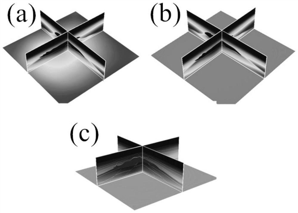
[0047] image 3 It is a schematic diagram of the P-wave velocity of the SEG-3D-anisotropy model in an embodiment of the present invention, image 3 (a) is the vertical P-wave velocity of the model, image 3 (b) is the P-wave velocity in the direction of the anisotropy parameter e of the model, image 3 (c) is the P-wave velocity in the direction d of the anisotropy parameter of the model. Figure 4 It is a structural schematic diagram of the observation system of the SEG-3D-anisotropic model in an embodiment of the present invention; the observation system is 33 shot lines, each shot line has 101 shots, a total of 3333 shots (0000-3332), each shot 401 * 401 (160801) channels receive, the shot distance is 120m, the shot line distance is 360m, and the long...
Embodiment 3
[0049] Based on the same inventive concept, this embodiment discloses that the present invention also provides a system for extracting azimuth gathers based on offset vector slices, including:
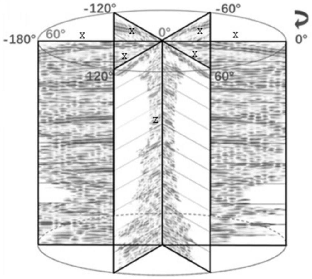
[0050] The reflection angle distribution map module is used to select several x-axes in a plane according to the preserved subsurface scattering azimuth, the x-axis is used to represent the angle change of the emission angle, the normal direction of the plane is the z-axis, and the z-axis is used to represent the formation Depth change, the reflection angle is marked in the x-z coordinate system to obtain the reflection angle distribution map; the azimuth angle gather acquisition module is used to obtain the azimuth angle gather according to the reflection angle distribution map.
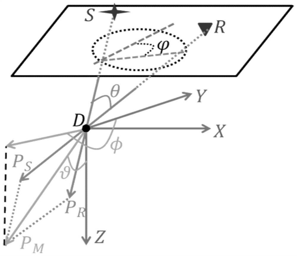
[0051] Among them, the formula for calculating the scattering azimuth angle is:
[0052]
[0053] Among them, P M is the sum of the incident slowness vector and the scattered slowness vector; P R is the...
PUM
 Abstract
Description
Claims
Application Information
 - R&D
- Intellectual Property
- Life Sciences
- Materials
- Tech Scout
- Unparalleled Data Quality
- Higher Quality Content
- 60% Fewer Hallucinations
Browse by: Latest US Patents, China's latest patents, Technical Efficacy Thesaurus, Application Domain, Technology Topic, Popular Technical Reports.
© 2025 PatSnap. All rights reserved.Legal|Privacy policy|Modern Slavery Act Transparency Statement|Sitemap|About US| Contact US: help@patsnap.com


