Eureka AIR delivers breakthrough ideas for toughest innovation challenges, trusted by R&D personnel around the world.

Tunable dispersion compensator designing and making method

A technology of dispersion compensator and design method, which is applied in the directions of eliminating distortion/dispersion, coupling of optical waveguides, electromagnetic wave transmission systems, etc., can solve the problems of large sampling period variation range, difficult fabrication, and incomplete realization of equivalent conversion, etc. Achieve the effect of improving performance, simplifying the production process, and avoiding chirp

Inactive Publication Date: 2005-07-20
TSINGHUA UNIV
View PDF1 Cites 8 Cited by
  • Summary
  • Abstract
  • Description
  • Claims
  • Application Information

AI Technical Summary

Problems solved by technology

[0005] Although this method realizes the design and manufacture of an equivalent nonlinear chirped fiber grating using a uniform template, the sampling period will vary greatly in the specific design, which brings some difficulties to the production
In addition, it uses the method of double exposure to make the grating, and it is easy to introduce additional chirp during the grating manufacturing process.
This method does not fully realize the flexible equivalent conversion of CSP and CGP

Method used


Image

  • Tunable dispersion compensator designing and making method
  • Tunable dispersion compensator designing and making method
  • Tunable dispersion compensator designing and making method

Examples


Embodiment Construction

[0059] The manufacturing method of the tunable dispersion compensator of the present invention is divided into two parts: one is the design of the apodized sampling fiber grating of the quadratic delay curve, and the other is the manufacture of the tunable dispersion compensator. Concrete implementation example is described in detail as follows in conjunction with accompanying drawing:

[0060] 1. Design of fiber grating used in tunable dispersion compensator

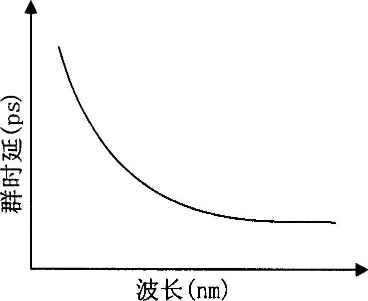
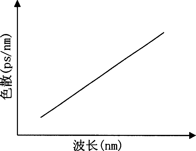
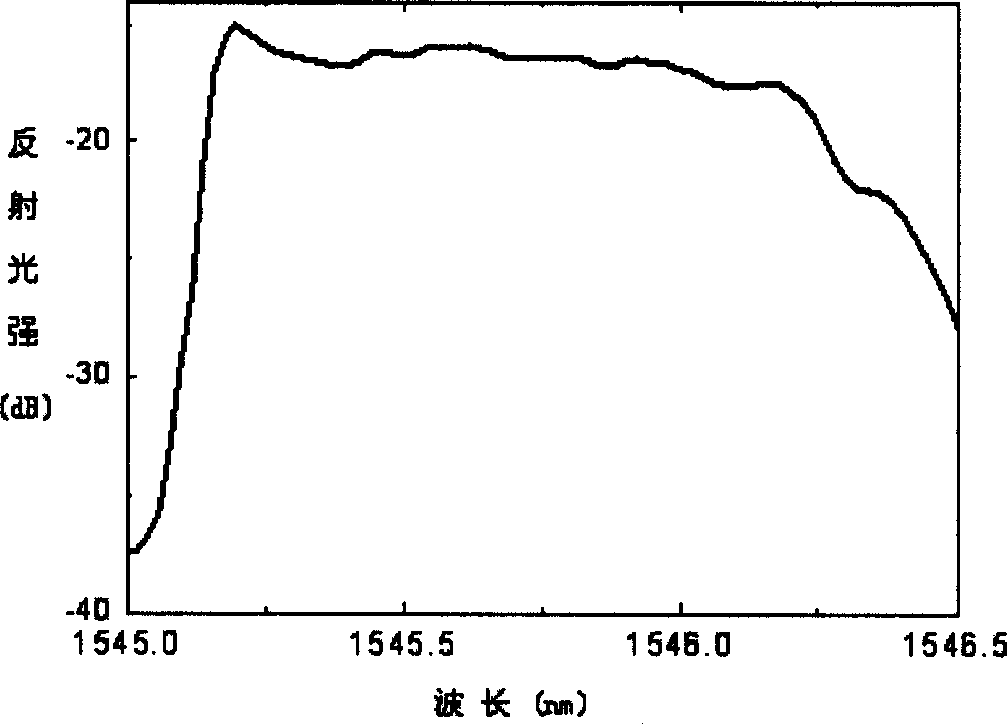
[0061] The equivalent chirp of the tunable dispersion grating required by the design is: Λ -1 =Λ -1,0 (1+cz 1 / 2 ), take Λ -1,0 =1545.7nm, c=3×10 -4 (mm) -1 / 2 .

[0062] For formula (4), take Z 0 = 0.28 mm. Get a=0.037(mm) from formula 2 -1 / 2 . The chirp coefficient c' of the linear chirp template is 0.048nm / mm, thus obtaining b=0.0024(mm) -1 , using Hamming apodization κ ( z ) = 1 + H ...


PUM


Abstract

The design and production of tunable dispersive compensator belongs to the fiber communications technological field. The hard core of this invention is a hit-the-toe sampling fiber raster with a twice time lag curve. The fiber raster adopts a linear chatter phasic templet production, and uses the chatter sampling period (CSP) to compensate the chatter grating period (CGP) from the templet to make the change bound of the raster sampling period narrow and then to make the producing process more simply and more steady. Otherwise in the design and producing process of the fiber raster, compensate the average refractive index change from the toe-hit by introducing the CSP. Therefore the production and toe-hit can be complete at a time in which just once exposal is needed. Finally fix the fiber raster on the exact mechanical tuning device, to extend the fiber raster under the control of microcomputer and then control the dispersive compensatory quantity.

Description

technical field [0001] The design and manufacturing method of a tunable dispersion compensator belongs to the technical field of optical fiber communication, and particularly relates to the field of fiber grating manufacturing. Background technique [0002] Generally, fiber dispersion compensation can be realized by using dispersion compensating fiber or dispersion compensating devices, such as dispersion compensating fiber grating, dispersion compensating etalon, etc. The implementation method of this dispersion compensation is fixed, and once the system is designed, the amount of dispersion compensation cannot be changed. The accumulation of dispersion is a process that changes with time. The system will be disturbed by many external factors, resulting in dynamically changing dispersion. This requires a dynamically tunable dispersion compensation device to monitor and track the changing dispersion. Compensation. Among them, the implementation of tunable dispersion is the ...

Claims


Application Information

Patent Timeline
Patent Type & Authority Applications(China)
IPC IPC(8): G02B6/26G02B6/34H04B10/2513
Inventor 姜典杰陈向飞戴一堂夏历谢世钟
Owner TSINGHUA UNIV
Why Eureka
Eureka Blog
Learn More