
Electronic equipment

A technology of electronic equipment and power feeding, which is applied in the field of communication and can solve the problem of narrow band coverage of antenna modules

Inactive Publication Date: 2020-07-31
VIVO MOBILE COMM CO LTD
View PDF5 Cites 2 Cited by
  • Summary
  • Abstract
  • Description
  • Claims
  • Application Information

AI Technical Summary

Problems solved by technology

[0003] An embodiment of the present invention provides an electronic device to solve the problem that the coverage of the antenna module of the current electronic device is relatively narrow

Method used


Image

  • Electronic equipment
  • Electronic equipment
  • Electronic equipment

Examples


Embodiment Construction

[0015] The following will clearly and completely describe the technical solutions in the embodiments of the present invention with reference to the accompanying drawings in the embodiments of the present invention. Obviously, the described embodiments are some of the embodiments of the present invention, but not all of them. Based on the embodiments of the present invention, all other embodiments obtained by persons of ordinary skill in the art without creative efforts fall within the protection scope of the present invention.

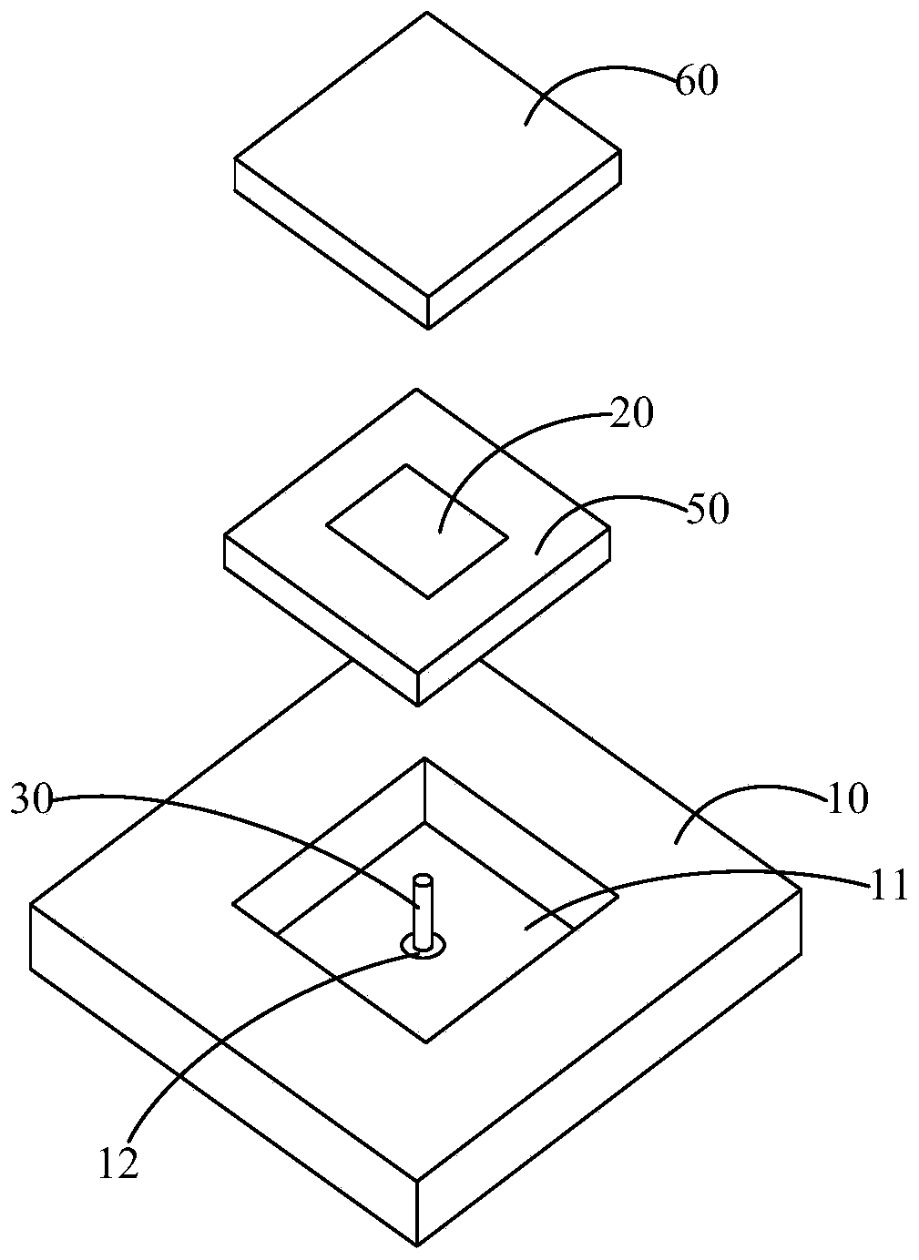
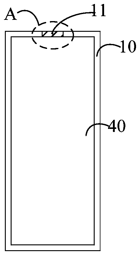
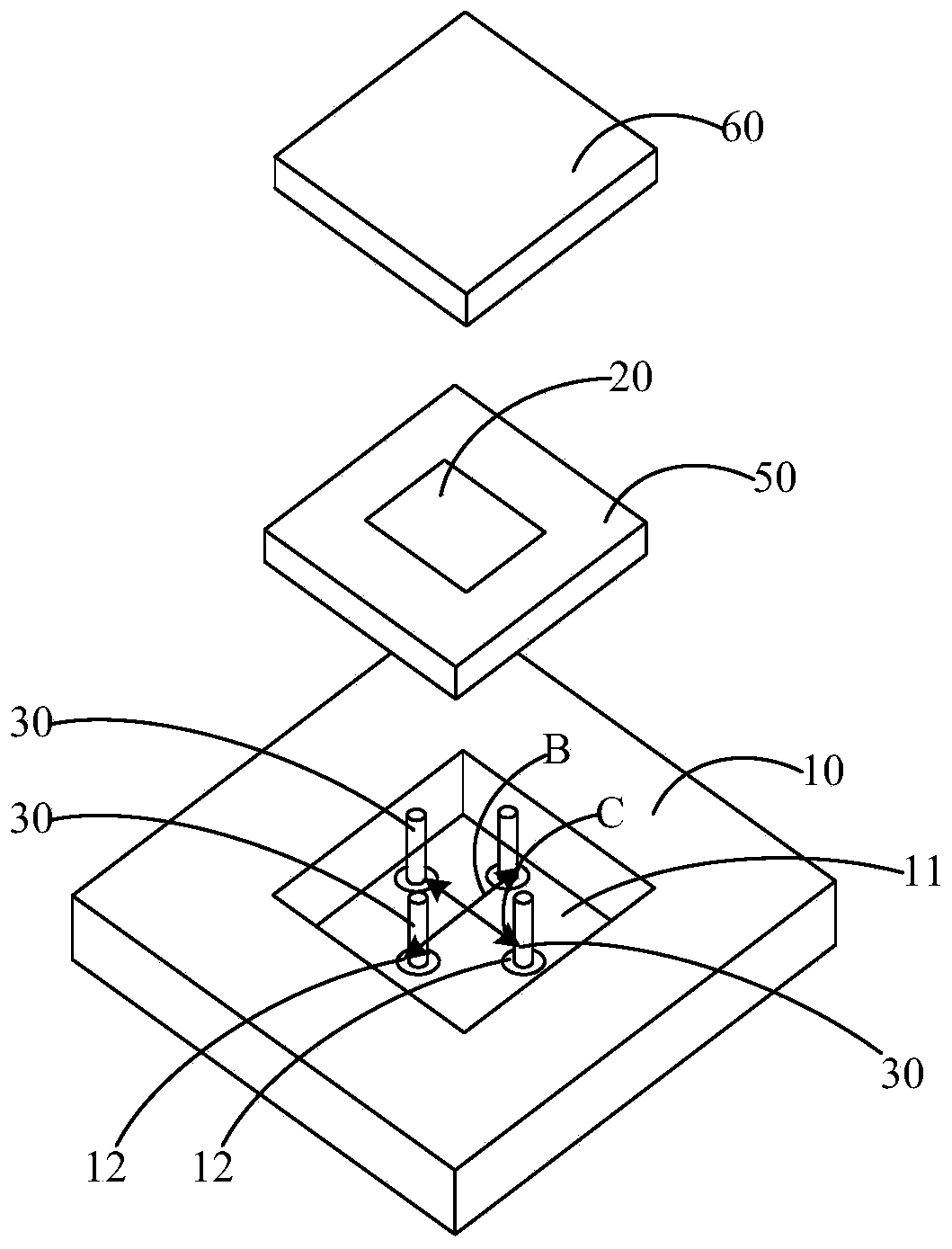
[0016] see figure 1 , figure 1 is a schematic structural diagram of an electronic device provided by an embodiment of the present invention, and figure 1 can be figure 2 A magnified view of the structure in region A shown in . Such as figure 1 As shown, the electronic device includes: a metal frame 10, a first insulating dielectric body 20, and a feed pin 30, the metal frame 10 is provided with an accommodating groove 11, and the first insulating ...


PUM


Abstract

The invention provides electronic equipment, which comprises a metal frame, a first insulating dielectric body and a feed pin, wherein an accommodating groove is formed in the metal frame, the first insulating dielectric body is at least partially arranged in the accommodating groove, a feed through hole is formed in the accommodating groove, the feed pin is arranged in the first insulating dielectric body in a penetrating manner through the feed through hole, and the first insulating dielectric body generates electromagnetic radiation under the action of an excitation signal input by the feedpin. According to the invention, the feed pin and the first insulating dielectric body can form a dielectric resonant antenna, and the side wall and the groove bottom of the accommodating groove canbe used as reflectors of the antenna, so that the gain of the antenna is enhanced, namely, the radiation performance of the antenna is enhanced; and the accommodating groove is formed in the metal frame, so that the influence of other parts of the electronic equipment on the radiation performance of the antenna can be reduced so as to further enhance the radiation performance of the antenna.

Description

technical field [0001] The present invention relates to the technical field of communication, in particular to an electronic device. Background technique [0002] With the development of electronic technology, current electronic devices generally need to be provided with antennas, so that the electronic devices have functions such as communication and network access. In actual use, an antenna installation space is generally reserved inside the electronic device, but due to interference from other components of the electronic device, the radiation performance of the antenna of the electronic device is poor. Contents of the invention [0003] An embodiment of the present invention provides an electronic device, so as to solve the problem that the antenna module of the current electronic device has a relatively narrow coverage range of a band. [0004] In order to solve the above-mentioned technical problems, an embodiment of the present invention provides an electronic devi...

Claims


Application Information

Patent Timeline
IPC IPC(8): H01Q1/52H01Q1/36H01Q1/50H01Q5/10H01Q5/28H01Q5/50H01Q15/14
CPCH01Q1/36H01Q1/50H01Q1/52H01Q15/14H01Q5/10H01Q5/28H01Q5/50
Inventor 邾志民王义金简宪静韩永健
Owner VIVO MOBILE COMM CO LTD
Learn More