LED chip mounter pick-and-paste path optimization method based on hybrid genetic algorithm
A hybrid genetic algorithm and LED placement machine technology, applied in the field of electrical technology and electrical engineering, can solve the problems of low LED patch production work efficiency, long pick-up and placement path, limited search ability, etc., and achieve optimal allocation and path problems. The method is fast and effective, improving production efficiency, and the effect of large search space
- Summary
- Abstract
- Description
- Claims
- Application Information
AI Technical Summary
Problems solved by technology
Method used
Image

Examples
specific Embodiment approach 1
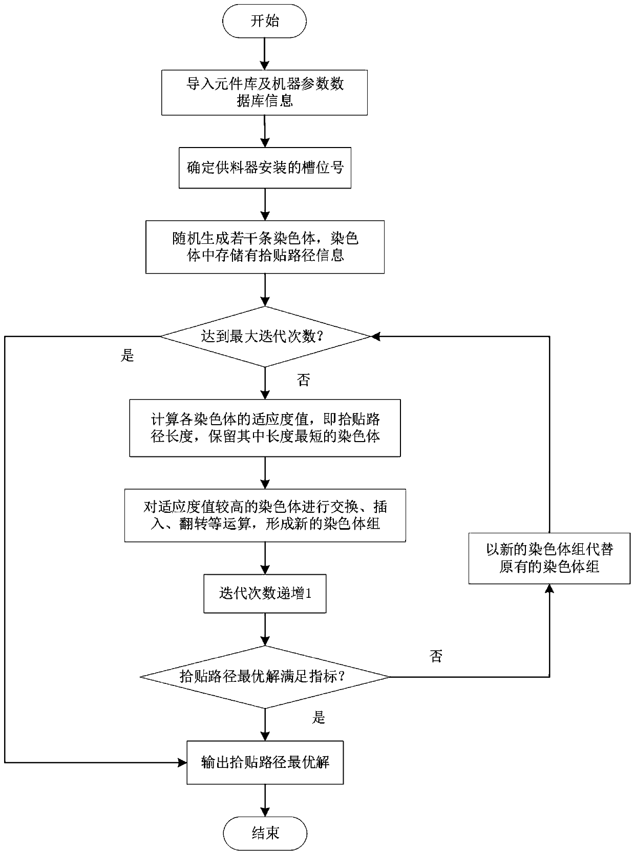
[0042] Specific implementation mode one: the specific process of a method for optimizing the pick-and-place path of LED placement machine based on hybrid genetic algorithm in this implementation mode is as follows:
[0043] Step 1. Preparatory work before production, importing machine parameters and PCB data file information;
[0044] Step 2. According to the machine parameters determined in step 1 and the PCB data file information, determine the feeder slot allocation position that makes the placement head move the shortest distance;
[0045] Step 3. Plan the pick-and-place path of the parallel chip mounter, use the midpoint of the feeder slot allocation determined in step 2 as the starting point and end point of the pick-and-place path optimization, use the hybrid genetic algorithm to search for a feasible solution to the pick-and-place path, and keep The solution with the shortest mounting path;
[0046] Step 4: Output the solution with the shortest mounting path found in st...
specific Embodiment approach 2
[0048] Specific embodiment two: the difference between this embodiment and specific embodiment one is: the preparatory work before production in described step one, import machine parameter and PCB data file information; Concrete process is:
[0049] Step 11: Import the coordinate information of the mounting point;
[0050] Before the pick and place optimization of the placement machine, it is necessary to import the production data information in advance, that is, the PCB data file. The PCB data file contains information such as component name, component type, X-axis and Y-axis coordinates of the component;
[0051] It is stipulated that when the operator is facing the machine, the lower left corner of the PCB circuit board is the reference origin, and the right and front of the operator are the growth directions of the X-axis and Y-axis respectively, Cp x (c) indicates the X-axis coordinates of component c relative to the reference origin, Cp y (c) indicates the Y-axis coor...
specific Embodiment approach 3
[0055] Specific embodiment three: the difference between this embodiment and specific embodiments one to two is: in the second step, according to the machine parameters determined in the step one and the PCB data file information, determine the feeder slot that makes the placement head move the shortest distance Assign location; the specific process is:
[0056] Step 21: Calculate the average coordinates of the components to be picked and pasted:
[0057] aveCp x =[Cp x (1)+Cp x (2)+…+Cp x (numCp)] / numCp,
[0058] In the formula, aveCp x is the average coordinate of the component to be picked; Cp x (1) Indicates the X-axis coordinates of component 1 relative to the reference origin; Cp x (numCp) represents the X-axis coordinates of the element numCp relative to the reference origin;
[0059] Step 22: Calculate the slot number corresponding to the center position of the feeder group, so that the center coordinates of the feeder group aveFeeder x As close as possible to...
PUM
 Abstract
Description
Claims
Application Information
 - R&D
- Intellectual Property
- Life Sciences
- Materials
- Tech Scout
- Unparalleled Data Quality
- Higher Quality Content
- 60% Fewer Hallucinations
Browse by: Latest US Patents, China's latest patents, Technical Efficacy Thesaurus, Application Domain, Technology Topic, Popular Technical Reports.
© 2025 PatSnap. All rights reserved.Legal|Privacy policy|Modern Slavery Act Transparency Statement|Sitemap|About US| Contact US: help@patsnap.com