
A lifting device based on a computer room controller

A computer network and lifting device technology, applied in the direction of supporting machines, servers, mechanical equipment, etc., can solve problems such as injury to operators, short circuits, and large electrical load on the controller, to avoid short circuit problems, facilitate collection and guidance, and facilitate cleaning effect

Active Publication Date: 2021-05-18
南通海赛未来数字科技有限公司
View PDF15 Cites 0 Cited by
  • Summary
  • Abstract
  • Description
  • Claims
  • Application Information

AI Technical Summary

Problems solved by technology

[0006] In order to solve the above-mentioned technical problems, the present invention provides a lifting device based on a computer network computer room controller to solve the problem that during the use of the controller, since the controller is connected to various devices, the electrical load of the controller is relatively large, which is very easy to Affected by the static electricity generated by the dust, it is easy to short-circuit in serious cases, and even injure the operator. In addition, mice in the computer room gnaw on the wiring harness or control, which is also a major problem in the use of the controller. Conventional The problem that rats can climb easily

Method used


Image

  • A lifting device based on a computer room controller
  • A lifting device based on a computer room controller
  • A lifting device based on a computer room controller

Examples


Embodiment

[0035]Appendfigure 1 AdherentFigure 8Down:

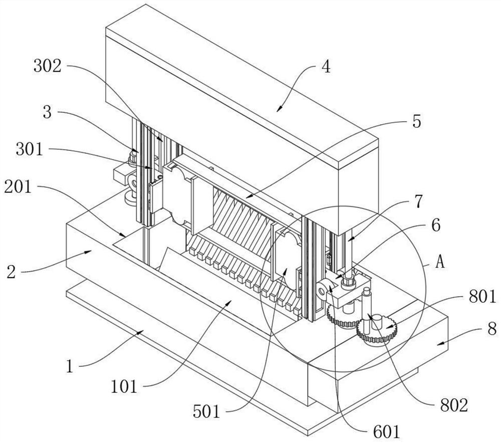
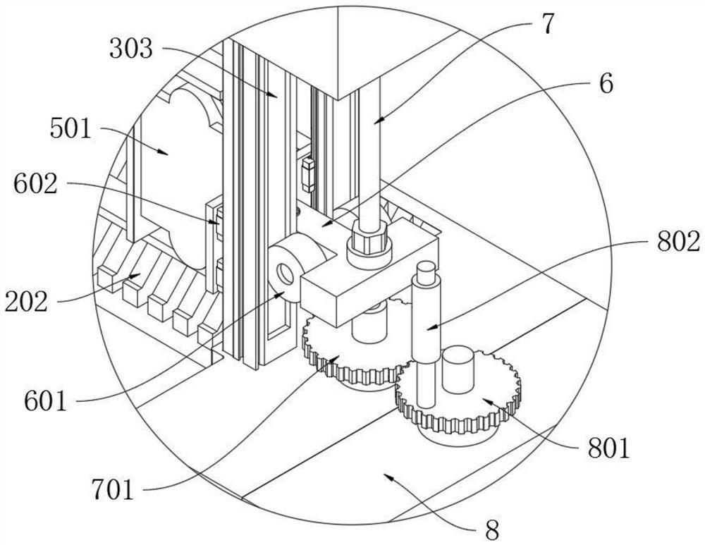
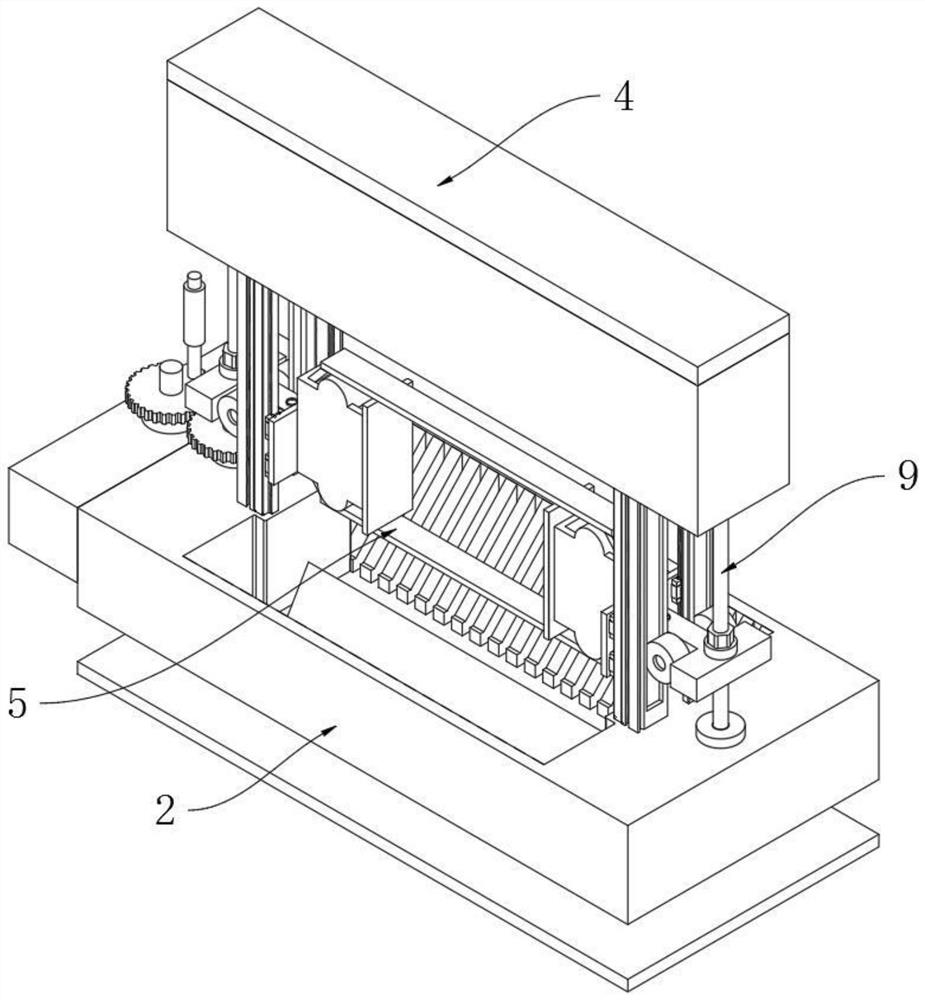
[0036]The present invention provides a lifting device based on a computer network, including a bottom plate 1; an upper end of the bottom plate 1 fixedly mounted a horizontal return operation table 2; the left end and right ends of the top plane of the operating table 2 are vertically fixed vertically. Installing a gantry 3; the upper outer cover of the two lift frames 3 has a protective cover 4; a drive mechanism 8 is coupled to the right side wall of the operating table 2;

[0037]The operating table 2 at the right side of the right end is vertically rotated, and the drive screw 7 is mounted, and the lower end of the driving screw 7 is engaged with the upper end of the drive mechanism 8; the left side of the left end lift 3 The coupling thread rod 9 is vertically rotated on the stage 2; the drive screw 7 and the upper end of the drive screw 7 and the driven screw 9 are connected by the belt 10; the lift 3 is slidably mounted on the mounting o...


PUM


Abstract

The invention provides a lifting device based on a controller in a computer network computer room, which relates to the technical field of controller auxiliary devices, to solve the problem that during the use of the controller, since the controller is connected to various devices, the electrical load of the controller is relatively large. It is very susceptible to the influence of static electricity generated by dust. In serious cases, it is prone to short-circuit phenomenon, and even the problem of injuring the operator. In addition, mice in the computer room gnaw on the wiring harness or control, which is also a major problem in the use of the controller. , the conventional frame body mouse can easily climb the problem, including the base plate; the upper end of the base plate is fixedly installed with a horizontal back-shaped operation table. In the present invention, since the middle part of the top plane of the bottom plate is horizontally fixed with a triangular column-shaped dust-separating block, more importantly, through the special structure composed of the dust-separating block and the guide grid, the phenomenon of damage to the controller by the mouse climbing frame is prevented from occurring. , in order to better protect the controller.

Description

Technical field[0001]The present invention relates to the field of controller auxiliary devices, and more particularly to a lifting device based on a computer network machine room controller.Background technique[0002]The controller refers to the main circuit or the resistance value of the main circuit or the control circuit in the predetermined order and the resistance value in which the electric resistance value is changed to control the start, speed, brake, and reverse main means of the motor. It consists of program counters, instruction registers, instruction decoders, timing generator, and operation controllers, it is a "decision-making body" published command, that is, the operation of coordination and directing the entire computer system.[0003]In the room, it is convenient to operate the controller, and there is usually a lifting device, such as a computer network controller lifting device in CN201520363962.3, including a bottom plate, a support pin on the bottom plate, and th...

Claims


Application Information

Patent Timeline
Patent Type & Authority Patents(China)
IPC IPC(8): H05K7/14H05K7/18F16M11/18F16M11/24
CPCF16M11/18F16M11/24H05K7/1461H05K7/1488H05K7/1497H05K7/183
Inventor 夏利玲顾建华
Owner 南通海赛未来数字科技有限公司
Learn More