An automatic coloring machine for round wooden boards
A plank, automatic technology, applied in the direction of spraying device, device for coating liquid on the surface, coating, etc., can solve the problems of time-consuming and low efficiency, and achieve the effect of reducing manual operation
- Summary
- Abstract
- Description
- Claims
- Application Information
AI Technical Summary
Problems solved by technology
Method used
Image
Examples
Embodiment 1
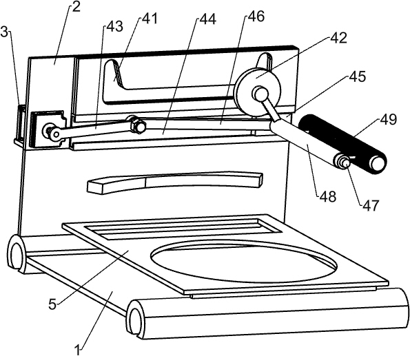
[0043] An automatic coloring machine for round wooden boards, such as Figure 1-3 As shown, it includes a color application seat 1, a mounting plate 2, a gear motor 3, a color application mechanism 4, a support plate 5 and a placement mechanism 6, and the left side of the color application seat 1 is provided with a mounting plate 2, and the upper middle part of the front side of the mounting plate 2 Geared motor 3 is provided, mounting plate 2 right sides are provided with paint-painting mechanism 4, and geared motor 3 is connected with paint-painted mechanism 4, and support plate 5 is installed on the top of paint-painting seat 1, and support plate 5 top is provided with placement mechanism 6.
[0044] When coloring the circular plank 7, first place the circular plank 7 on the placing part of the placement mechanism 6, manually spray a layer of paint on the surface of the circular plank 7, and start the deceleration when the paint is not dry Motor 3, the output shaft of reduc...
Embodiment 2
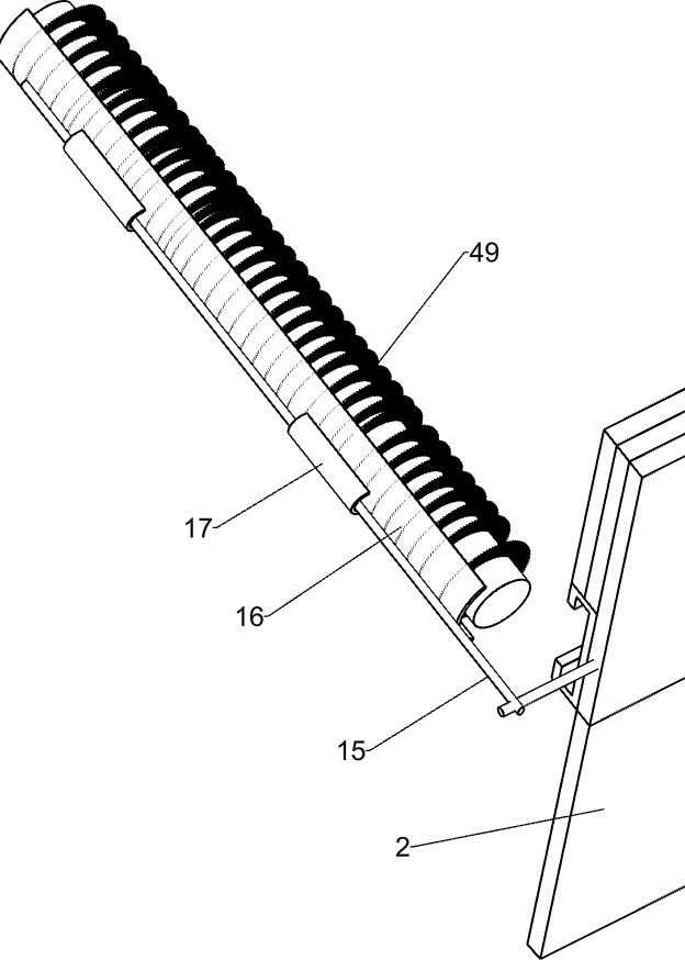
[0046] Specifically, such as Figure 1-3 As shown, the coloring mechanism 4 includes a disc 42, a swing lever 43, a slide block 45, a connecting rod 46, a round head rod 47, an installation cover 48 and a coloring roller brush 49, and the output shaft of the reduction motor 3 is connected with the swing lever 43 , the end of the swing rod 43 is rotated to be provided with a connecting rod 46, the upper part of the right side of the mounting plate 2 is provided with an upper chute 41, and a disc 42 is slidably installed in the upper chute 41, and the middle and upper part of the right side of the mounting plate 2 is provided with a sliding chute 44, slide block 45 is provided with sliding type in sliding groove 44, and round head bar 47 is installed on the right part of slide block 45, and the end of connecting rod 46 is connected with the left side of round head bar 47 rotationally, and round head bar 47 is covered with installation sleeve 48, the disc 42 is connected with the...
Embodiment 3
[0051] In particular, according to figure 1 and Figure 4-6 As shown in the diagram, it also includes an upper bevel gear 8, a second shaft 9, a bevel gear with missing teeth 10, a third shaft 11, a lower bevel gear 12, a pulley 13 and a flat belt 14, and an upper cone is installed in the middle of the first shaft 65. Gear 8, bevel gear 10 with missing tooth bevel gear 10 is installed at the rear end of the second rotating shaft 9, the toothless bevel gear 10 can mesh with upper bevel gear 8, and the color-painting seat 1. The front left side rotating type is provided with a third rotating shaft 11, the right end of the third rotating shaft 11 and the front end of the second rotating shaft 9 are equipped with a lower bevel gear 12, the two lower bevel gears 12 are meshed, the output shaft of the reduction motor 3 and the second rotating shaft The left sides of the three rotating shafts 11 are provided with pulleys 13, and the two pulleys 13 are connected by flat belts 14.
...
PUM
 Abstract
Description
Claims
Application Information
 - R&D
- Intellectual Property
- Life Sciences
- Materials
- Tech Scout
- Unparalleled Data Quality
- Higher Quality Content
- 60% Fewer Hallucinations
Browse by: Latest US Patents, China's latest patents, Technical Efficacy Thesaurus, Application Domain, Technology Topic, Popular Technical Reports.
© 2025 PatSnap. All rights reserved.Legal|Privacy policy|Modern Slavery Act Transparency Statement|Sitemap|About US| Contact US: help@patsnap.com


