
Automatic welding device for capacitor leading-out soldering lug

A technology of automatic welding and capacitors, which is applied in the direction of auxiliary devices, welding equipment, auxiliary welding equipment, etc., to achieve the effects of convenient positioning, labor saving, and wide application range

Active Publication Date: 2020-08-04
深圳市鹏创鑫自动化设备有限公司
View PDF9 Cites 3 Cited by
  • Summary
  • Abstract
  • Description
  • Claims
  • Application Information

AI Technical Summary

Problems solved by technology

However, the hierarchical adjustment method of this structure is only suitable for several fixed sizes, and it is necessary to provide an automatic welding equipment with a wider application range that can realize stepless adjustment.

Method used


Image

  • Automatic welding device for capacitor leading-out soldering lug
  • Automatic welding device for capacitor leading-out soldering lug
  • Automatic welding device for capacitor leading-out soldering lug

Examples


Embodiment Construction

[0044] In order to make the object, technical solution and advantages of the present invention clearer, the present invention will be further described in detail below in conjunction with the accompanying drawings and embodiments. It should be understood that the specific embodiments described here are only used to explain the present invention, not to limit the present invention.

[0045] In the description of the present invention, it should be noted that the terms "center", "upper", "lower", "left", "right", "front", "rear", "vertical", "horizontal", The orientation or positional relationship indicated by "inner", "outer", etc. is based on the orientation or positional relationship shown in the drawings, and is only for the convenience of describing the present invention and simplifying the description, rather than indicating or implying that the referred device or element must have Certain orientations, constructed and operative in certain orientations, therefore are not t...


PUM


Abstract

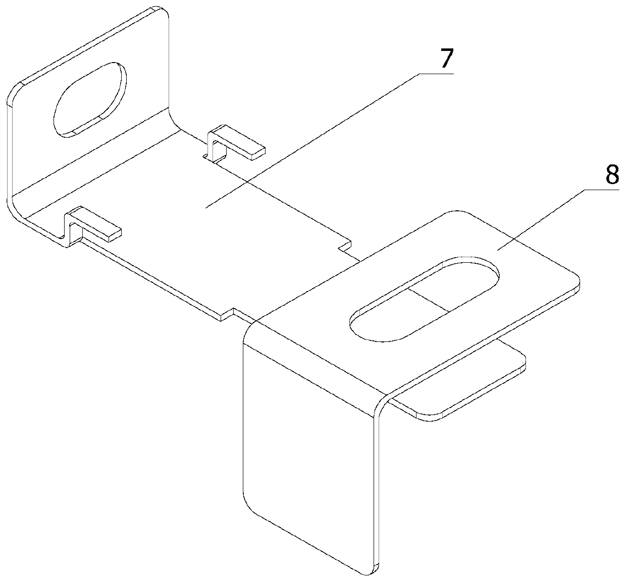
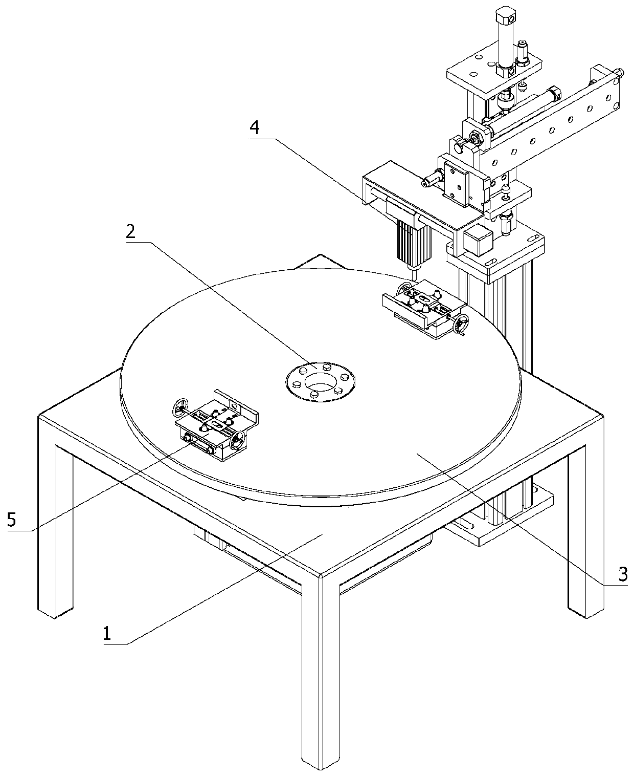
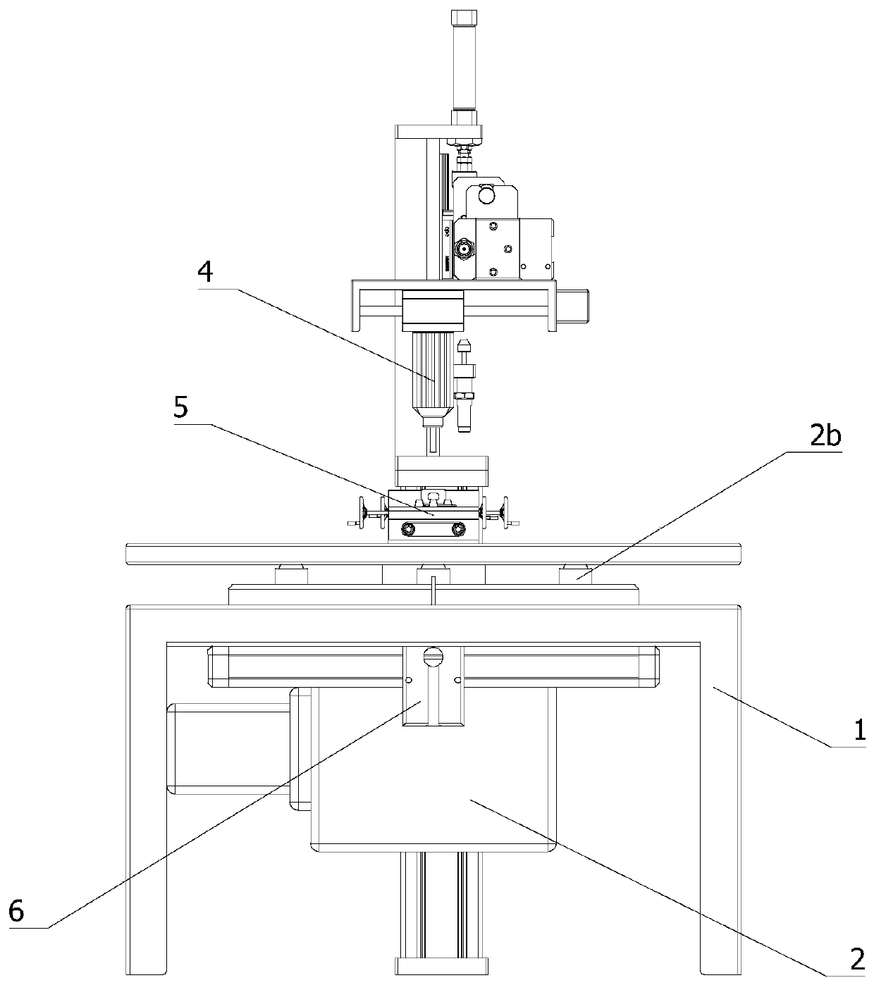
The invention relates to the technical field of automatic welding, in particular to an automatic welding device for a capacitor leading-out soldering lug. The automatic welding device comprises a rack, an indexing mechanism, a circular workbench, a welding mechanism, a workpiece jig, an ejection mechanism, a first soldering lug and a controller, wherein the workpiece jig comprises a first lateralclamping assembly, a second lateral clamping assembly and a workpiece positioning assembly; the indexing mechanism is mounted on the rack; the circular workbench is arranged on the indexing mechanism;the welding mechanism is arranged at one side of the circular workbench; the workpiece jig is arranged at the upper end of the circular workbench; the first lateral clamping assembly and the second lateral clamping assembly are separately arranged on a pair of side walls of the workpiece jig, and the first lateral clamping assembly is positioned above the second lateral clamping assembly; the workpiece positioning assembly is mounted on the upper end surface of the workpiece jig; and the ejection mechanism is arranged on the rack and is positioned below a loading end of the circular workbench. According to the scheme adopted by the invention, the automatic welding device can perform stepless regulation, is wide in scope of application, is convenient in positioning, saves labor power, is accurate in positioning, and is good in welding effect.

Description

technical field [0001] The invention relates to the technical field of automatic welding, in particular to an automatic welding device for lead-out solder tabs of capacitors. Background technique [0002] Capacitors have been widely used as electronic components for a long time. The existing capacitor pins are all connected after the main body of the capacitor is manufactured. As a traditional conductor connection method, welding has been used because of its stability and low cost. With the continuous development of the electronics industry, there are various requirements for the connecting pins of capacitors, and in the face of various pins of different specifications, they can only be soldered by hand, which results in low efficiency and high scrap rate. question. [0003] Chinese patent CN201420065516.X discloses a welding jig for capacitor lead-out lugs, including a backing plate, the backing plate is rectangular, one side of the backing plate is connected to a stopper,...

Claims


Application Information

Patent Timeline
Patent Type & Authority Applications(China)
IPC IPC(8): B23K37/00B23K37/02B23K37/04B23K101/36
CPCB23K37/0443B23K37/00B23K37/0461B23K37/0252B23K2101/36
Inventor 高星东
Owner 深圳市鹏创鑫自动化设备有限公司
Learn More