Automatic valve element assembling line

An assembly line and valve core technology, applied in engine components, engine lubrication, mechanical equipment, etc., can solve problems such as inability to adapt to valve core assembly, achieve good economic benefits, ensure product quality, and achieve the effect of automated production

Pending Publication Date: 2020-08-04
KAIPING SEDAL TAP COMPONENTS
View PDF3 Cites 8 Cited by
  • Summary
  • Abstract
  • Description
  • Claims
  • Application Information

AI Technical Summary

Problems solved by technology

Through comparative analysis, it is found that the structure and assembly method of the spools produced by different compa

Method used


Image

  • Automatic valve element assembling line
  • Automatic valve element assembling line
  • Automatic valve element assembling line

Examples


Embodiment Construction

[0041] The technical solutions in the embodiments of the present invention are clearly and completely described below in conjunction with the drawings in the embodiments of the present invention. It should be understood that the specific embodiments described here are only used to explain the present invention, and are not intended to limit the protection scope of the present invention.

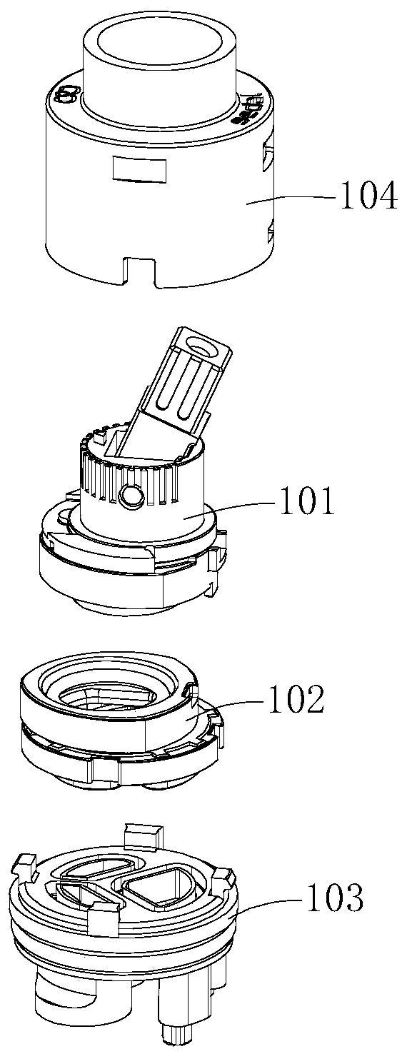
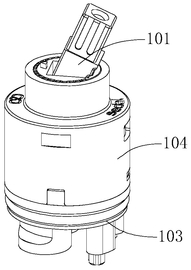
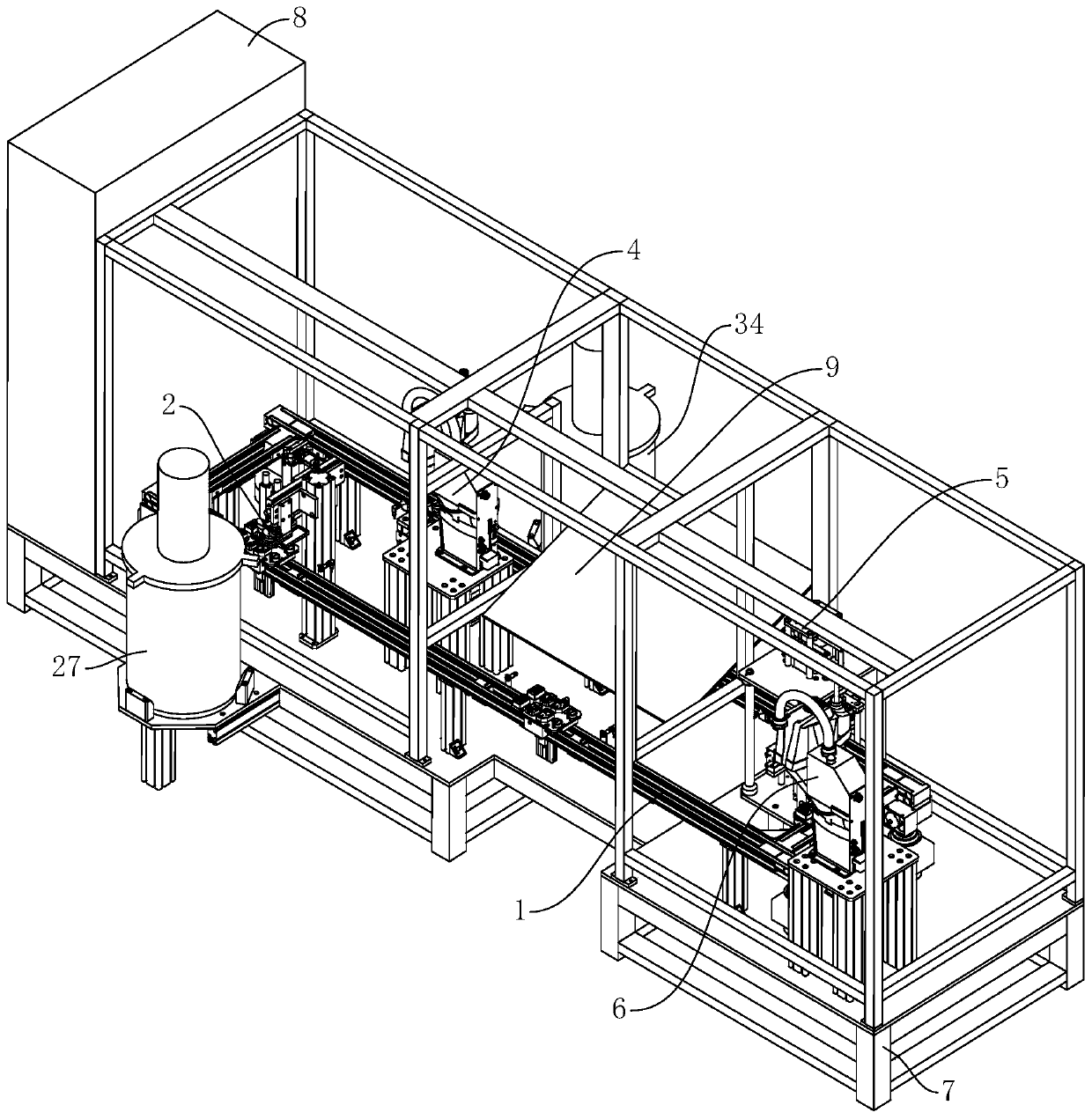
[0042] see Figure 1 to Figure 4 , the present invention provides an automatic valve core assembly line for assembling a valve stem assembly 101, a moving plate assembly 102, a stationary plate assembly 103 and a casing 104 into a valve core. The spool automatic assembly line includes a circulation conveying device 1 , a first fueling device 2 , a second fueling device 3 , an assembly device 4 , a testing device 5 , an inkjet printer (not shown in the figure) and a sorting manipulator 6 . The circulation conveying device 1 is used for conveying multiple parts of the valve core to various wor...


PUM


Abstract

The invention provides an automatic valve element assembling line which comprises a circular conveying device, a first oiling device, a second oiling device and an assembling device. The circular conveying device comprises a movable carrier. The carrier bears multiple components of a valve element to move to different stations to be machined, the first oiling device and the second oiling device are used for spraying lubricating oil to different components of the valve element, the assembling device is close to the second oiling device, and the assembling device comprises a positioning clampingmechanism and an assembling mechanical hand, the carrier is clamped and positioned through the positioning clamping mechanism so that the assembling mechanical hand can assemble the valve element components oiled by the first oiling device on the carrier and the valve element components needing no oiling, and the finally-assembled valve element components are assembled to a previous assembling piece after being oiled through the second oiling device. The automatic valve element assembling line can achieve automatic assembling of valve elements, and the production efficiency can be improved.

Description

technical field [0001] The invention relates to a valve core manufacturing equipment for a faucet, in particular to an automatic valve core assembly line. Background technique [0002] The spool is the core part of the faucet switch and the adjustment of hot and cold water. Such as figure 1 , 2 As shown, the spool produced by our company includes a valve stem assembly 101, a moving plate assembly 102, a static plate assembly 103, and a housing 104. These four components need to be combined in an orderly manner to form a spool, and the spool needs to be assembled during assembly. Lubricating oil is added to the moving plate assembly 102 and the stationary plate assembly 103 respectively. At present, the assembly of the spool is mostly done through an automated assembly line. After searching, it is found that there are relatively similar existing technologies as follows. For example, the invention patent with the application number CN201822083922.X discloses a large valve ...

Claims


Application Information

Patent Timeline
IPC IPC(8): B23P19/04B23P19/00F16N7/38F16N19/00F16N31/02
CPCB23P19/001B23P19/04F16N7/38F16N19/00F16N31/02
Inventor 欧阳投怀丁仕宝
Owner KAIPING SEDAL TAP COMPONENTS
Why Eureka
Try Eureka