
Plate edge grinding device for machining

A technology for machining and sheet metal, applied in the field of sheet edging devices for machining, can solve the problem that the edging device cannot adjust the position and angle of grinding, and achieve the effects of improving convenience, increasing bearing capacity and reducing friction.

Inactive Publication Date: 2020-08-04
程宏剑
View PDF1 Cites 4 Cited by
  • Summary
  • Abstract
  • Description
  • Claims
  • Application Information

AI Technical Summary

Problems solved by technology

[0004] Based on the technical problem that the existing edging device cannot timely adjust the grinding position and angle according to the actual situation, the present invention proposes a plate edging device for mechanical processing

Method used


Image

  • Plate edge grinding device for machining
  • Plate edge grinding device for machining
  • Plate edge grinding device for machining

Examples


Embodiment 1

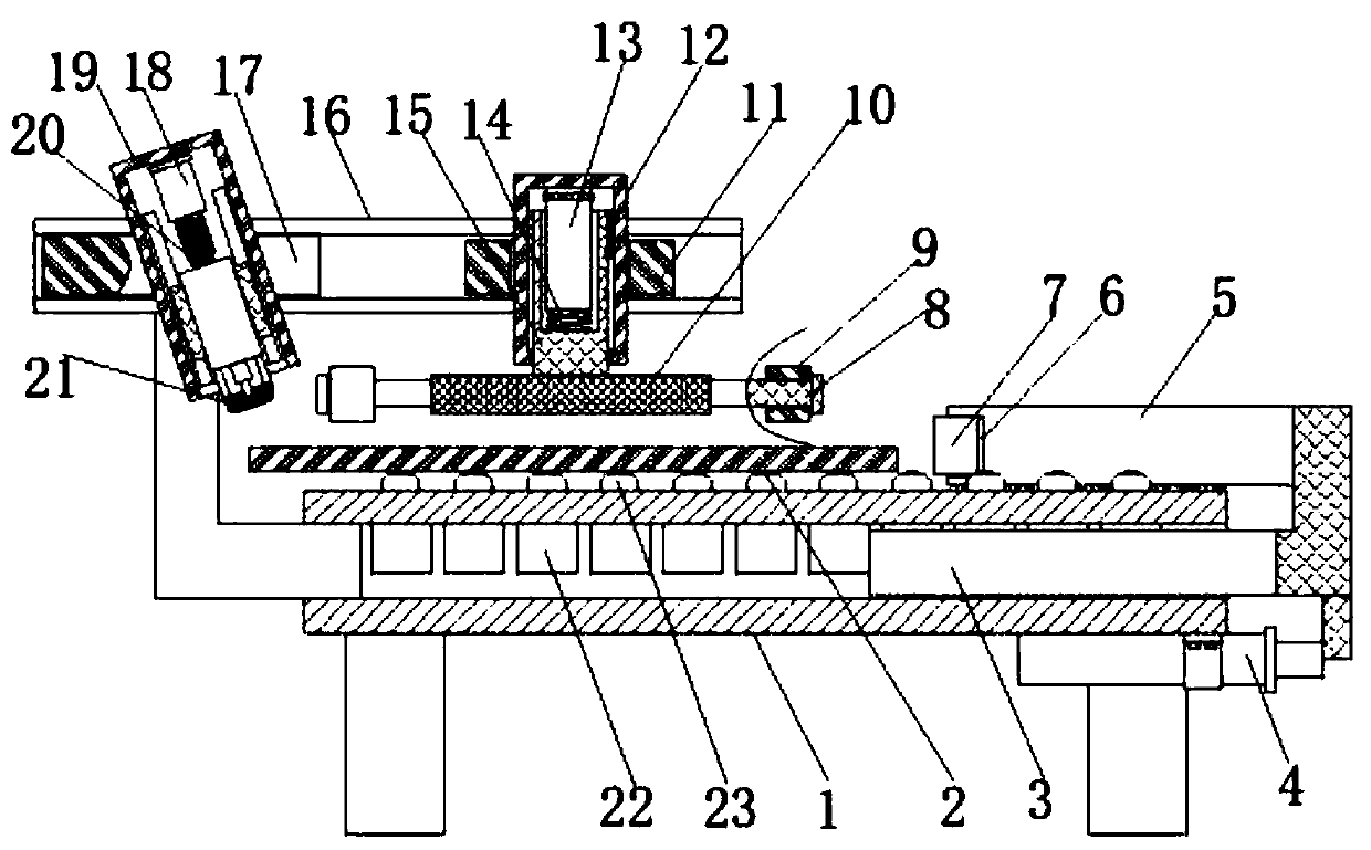
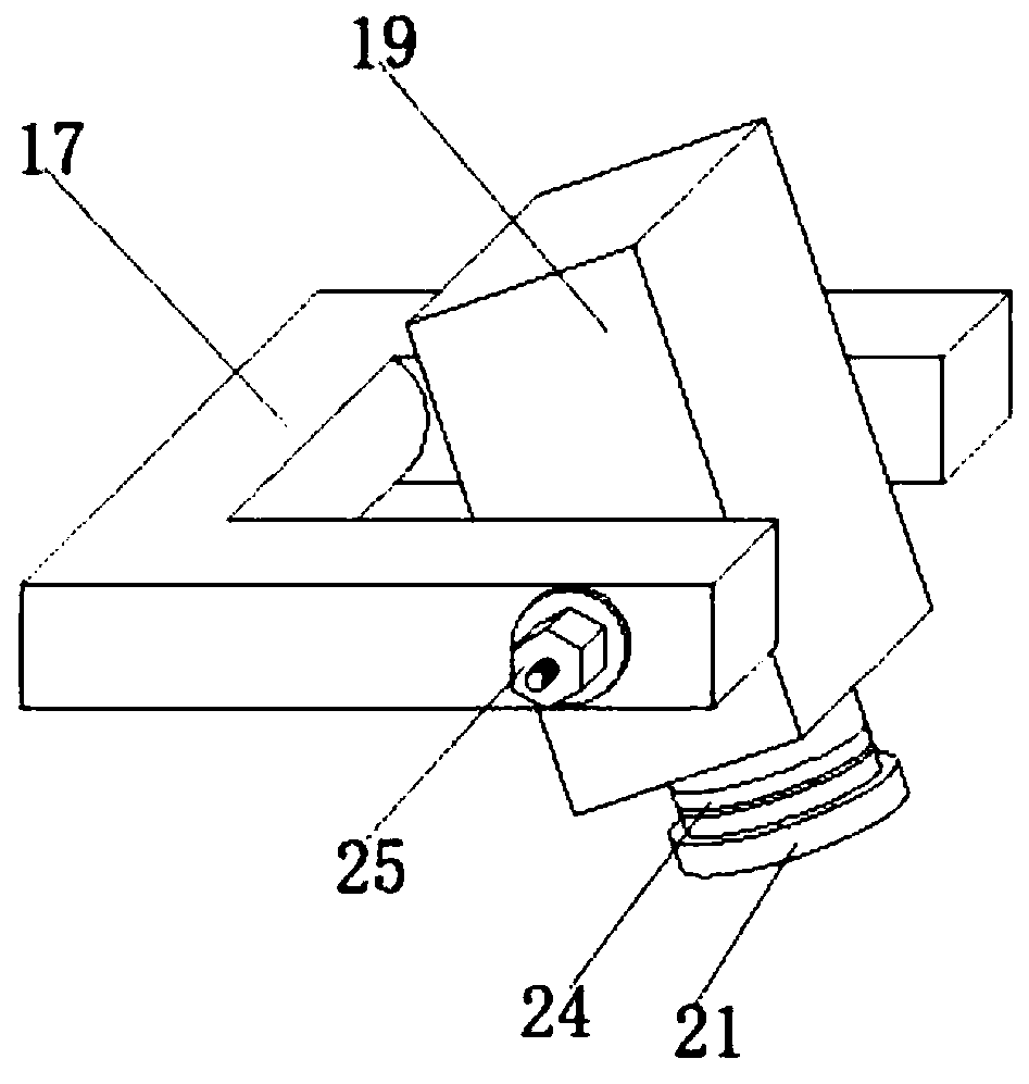
[0029] refer to Figure 1-5 , a plate edging device for mechanical processing, including a base 1 with a cavity in a flat square tube structure, one end of the base 1 is inserted with two mutually symmetrical L-shaped support frames, and the two L-shaped support frames Two channel-steel crossbeams 16 with opposite openings and parallel to each other are fixed on the top of the top, and C-shaped clamping blocks 17 and rectangular fixed frames 11 are respectively clamped between the two channel-steel beams 16 near the two ends. The middle of the C-shaped clamping block 17 A motor box 19 with an opening downward is clamped, and coaxially distributed elongated studs are respectively fixed on the opposite side outer walls of the motor box 19, and the outer walls of the studs are screwed with fastening bolts. When the angle of the motor box 19 is adjusted Can be screwed fastening bolt afterwards and motor case 19 is clamped, to fix the inclination angle of motor case 19, the inside ...

Embodiment 2

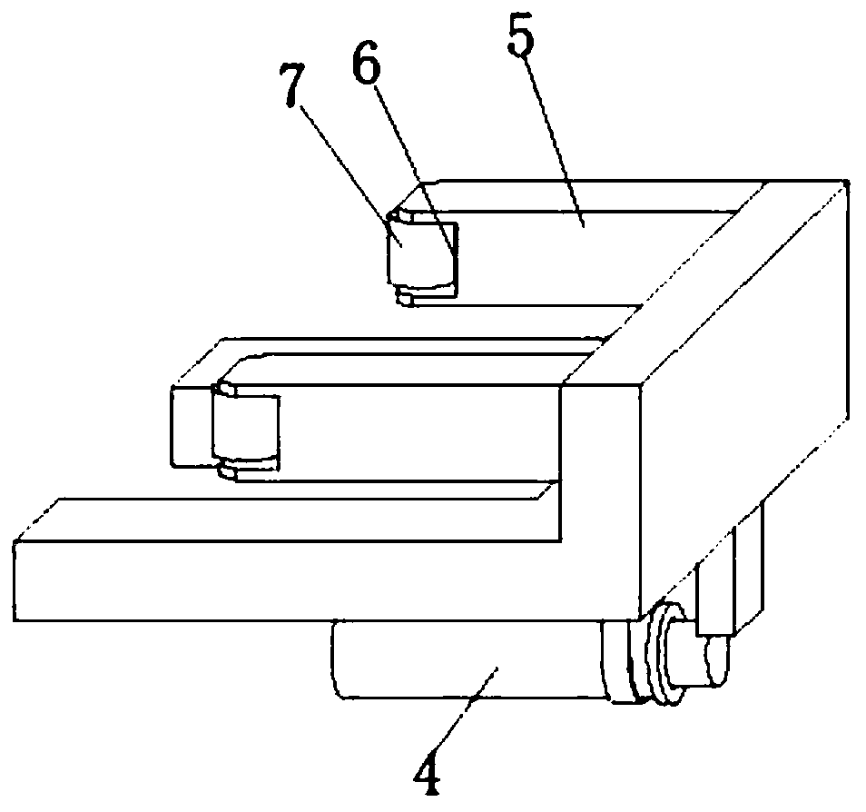
[0037] refer to figure 1 with image 3 , a plate edging device for mechanical processing. Compared with Embodiment 1, this embodiment also includes that the end of the bottom end of the base 1 away from the L-shaped support frame is fixed with a telescopic rod 4 by bolts, and the extension rod of the telescopic rod 4 is The end is fixed with a push block.

[0038] Wherein, one end of the base 1 close to the telescopic rod 4 is slidably connected with an L-shaped sliding plate 3 , and the side of the vertical plate of the L-shaped sliding plate 3 near the middle of the base 1 is fixed with two resisting rods 5 .

[0039] Wherein, gaps 6 are formed at the ends of the two resisting rods 5 away from the L-shaped sliding plate 3 , and rollers 7 are arranged in the gaps 6 .

[0040] Working principle: When in use, it can hold the edge of the plate body away from the grinding side tightly, and change the sliding friction into rolling friction, which plays a good guiding role.


PUM


Abstract

The invention belongs to the technical field of grinding devices, particularly relates to a plate edge grinding device for machining, and provides the following scheme for solving the problem that anexisting edge grinding device cannot adjust a grinding position and angle in time according to actual conditions. The plate edge grinding device comprises a base in which a cavity is of a flat squaretube structure; two symmetrical L-shaped supporting frames are inserted into one end of the base, two parallel channel steel cross beams with opposite openings are fixed to top ends of the two L-shaped supporting frames, and a C-shaped clamping block and a rectangular fixing frame are clamped to the positions, close to the two ends, between the two channel steel cross beams correspondingly; and amotor box with a downward opening is clamped in the middle of the C-shaped clamping block. According to the plate edge grinding device disclosed by the invention, when the edge of a plate needs to beground in the using process, the edge of the plate only needs to be moved to the position above the edge of the base, then the pressing plate is controlled to descend so as to rapidly press the plate,and meanwhile, the plate can be pushed to advance while being ground, and the grinding convenience is improved.

Description

technical field [0001] The invention relates to the technical field of plate grinding, in particular to a plate edge grinding device for mechanical processing. Background technique [0002] Machining refers to the whole process of using traditional machining methods to make the shape, size, relative position and properties of blanks into qualified parts according to the drawings and dimensions. Machining inevitably requires plate processing. During the process of plate processing Due to processing requirements, the plate needs to be edged. [0003] After retrieval, the Chinese patent No. CN201720883287.6 discloses a bamboo and wood board edging device, including an outer frame, and the top ends of the outer frame are respectively fixedly connected with a first fixed block and a second fixed block. A screw rod is fixedly connected between the first fixed block and the second fixed block, a slider is slidably connected to the surface of the screw rod, an upper splint is fixed...

Claims


Application Information

Patent Timeline
Patent Type & Authority Applications(China)
IPC IPC(8): B24B9/00B24B41/06B24B41/00
CPCB24B9/00B24B41/00B24B41/06
Inventor 胡昌荣
Owner 程宏剑
Learn More