Color masterbatch mixing device

A mixing device and color masterbatch technology, which are applied in the directions of cleaning hollow objects, chemical instruments and methods, cleaning methods and utensils, etc., can solve the problems of long cleaning time of remaining color masterbatches and uneven mixing of color masterbatches, saving downtime, The effect of improving mixing efficiency and speeding up cleaning efficiency

Pending Publication Date: 2020-08-04
常州海石智能装备有限公司
1 Cites 1 Cited by

AI-Extracted Technical Summary

Problems solved by technology

[0005] The purpose of the present invention is to provide a color masterbatch mixing device to solve the problem in the prior art that the remai...

Method used

The bottom of material receiving cavity is connected with fast material cleaning pipe 7, and fast material cleaning pipe 7 is communicated with feeding cavity, and the endoporus of fast material cleaning pipe 7 forms fast material cleaning port 71, and fast material cleaning pipe 7 is used for color supply The color masterbatch in the master hopper 3 falls under the action of gravity to realize quick removal. The fast cleaning pipe 7 is provided with an opening and closing valve 72, and the opening and closing valve 72 is used to control the opening and closing of the fast cleaning pipe 7. In this embodiment, the opening and closing valve 72 is a solenoid valve, and the response speed of the solenoid valve is fast, which facilitates automatic control.
The preferred embodiment of a kind of masterbatch mixing device of the present invention, as shown in Figure 1 to Figure 5, comprises main hopper 1, mixing seat 2, look masterbatch hopper 3, screw conveyor...

Abstract

The invention relates to the technical field of color masterbatch mixing machines, and discloses a color masterbatch mixing device which comprises a main hopper, a mixing seat, a color masterbatch hopper and a screw conveyer. The color masterbatch hopper is connected with the mixing seat through the screw conveyer; the screw conveyer communicates with the mixing seat through a sliding valve; the sliding valve comprises a valve body and a valve element arranged in the valve body; a residual material cleaning port is formed in the valve body; and the valve element is provided with a conveying position for communicating the screw conveyer and the mixing seat, and a cleaning position for communicating the screw conveyer and the residual material cleaning port in a moving stroke. The sliding valve is arranged between the screw conveyer and the mixing seat, an operator can control the sliding valve to move to a material cleaning position when a color masterbatch needs to be switched, and thescrew conveyer communicates with the residual material cleaning port, so that people can adopt an air blowing method to enable residual color masterbatches to be quickly cleaned by passing through the residual material cleaning port, the color masterbatch cleaning efficiency is improved, the main hopper and the stoppage time of the main hopper are saved, and the uniformity in mixing different color masterbatches and a main material is improved.

Application Domain

Technology Topic

EngineeringSpool valve +2

Image

  • Color masterbatch mixing device
  • Color masterbatch mixing device
  • Color masterbatch mixing device

Examples

  • Experimental program(1)

Example Embodiment

[0021] The specific implementation manners of the present invention will be further described in detail below in conjunction with the accompanying drawings and embodiments. The following examples are used to illustrate the present invention, but are not intended to limit the scope of the present invention.
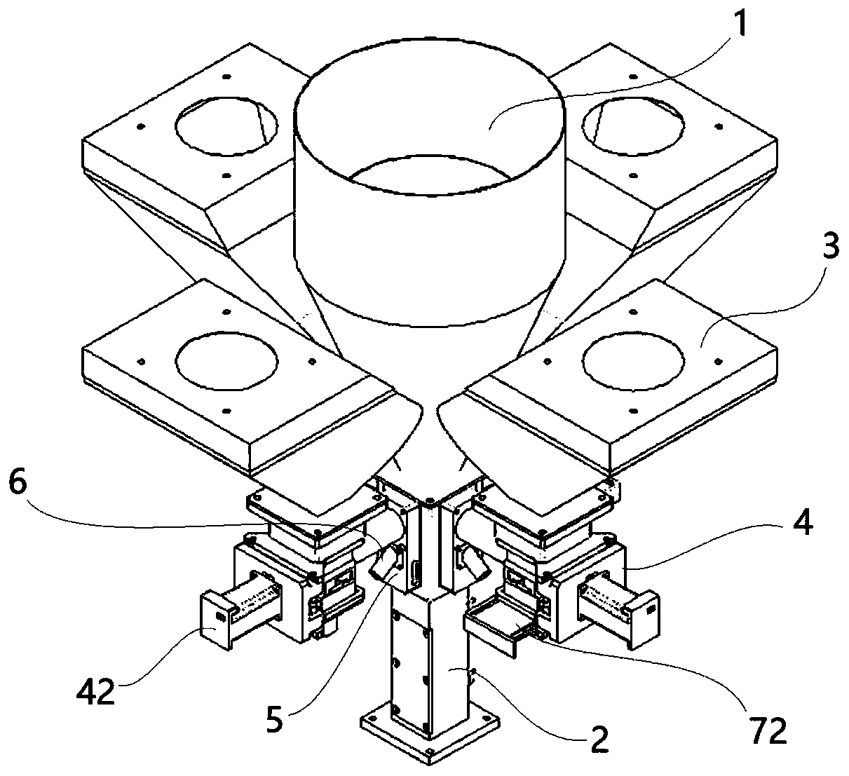
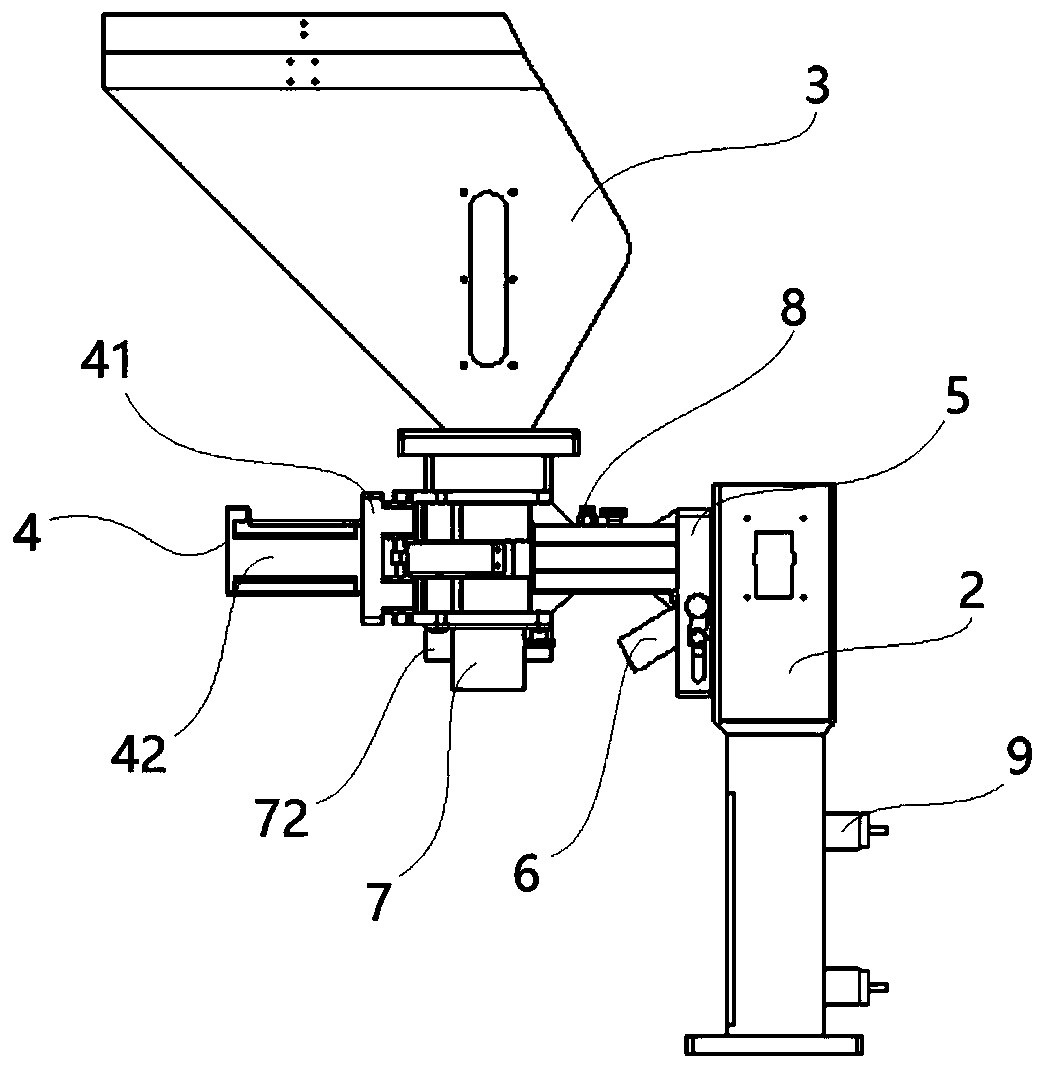
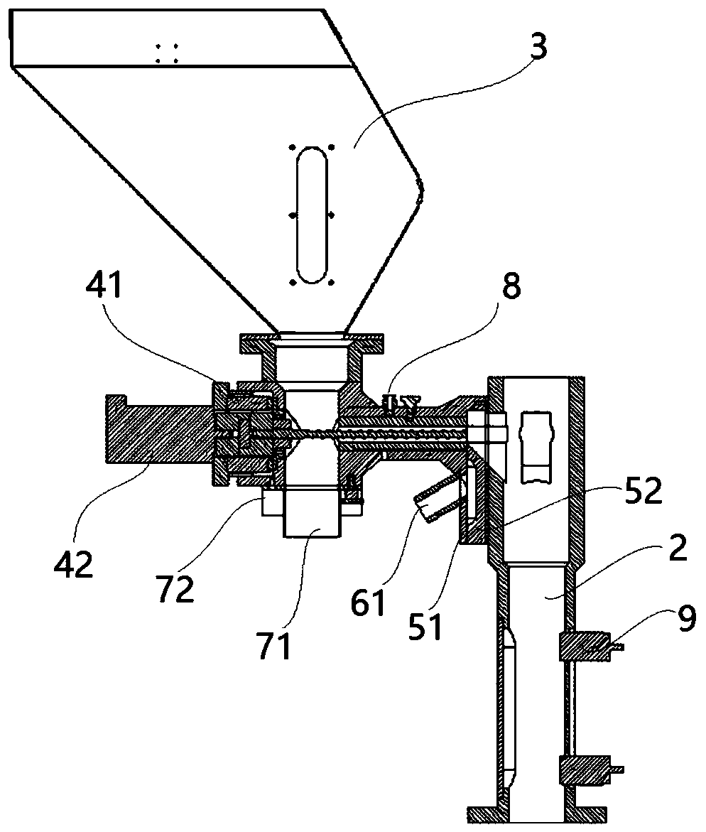
[0022] A preferred embodiment of a masterbatch mixing device of the present invention, such as Figure 1 to Figure 5 As shown, it includes main hopper 1, mixing seat 2, color master hopper 3, screw conveying device 4 and slide valve 5, main hopper 1 is arranged on the upper side of mixing seat 2, and the bottom of main hopper 1 is connected with mixing seat 2 Connected, the main hopper 1 is used to convey the main raw material. The color masterbatch hopper 3 and the mixing seat 2 are connected by a screw conveying device 4, the color masterbatch hopper 3 is used to accept the color masterbatch, the screw conveying device 4 is used to transport the color masterbatch to the mixing seat 2, and the mixing seat 2 is used for mixing The main raw material is connected with the color masterbatch, the screw conveying device 4 and the mixing seat 2 through a slide valve 5 . A material level sensor 9 is also arranged in the mixing seat 2. The material level sensor 9 is used to detect the position of the main raw material and the color masterbatch mixed in the mixing seat 2, and can transmit position signals to the control system to avoid excessive material overflow.
[0023] There are four color master hoppers 3, and the four color master hoppers 3 are arranged at intervals along the circumference of the main hopper 1. A screw conveyor 4 is connected between each color master hopper 3 and the mixing seat 2. Each color master hopper 3 can deliver different masterbatches to the mixing seat 2, and the four masterbatch hoppers 3 can work simultaneously and deliver the color masterbatch to the mixing seat 2, and can also work partially; in other embodiments, the color masterbatch hopper 3 can also work There can be two, three, or just one. The structure of the color masterbatch hopper 3 is the same as that of the prior art, and will not be described in detail here.
[0024] The screw conveying device 4 comprises a housing 41, a conveying screw 43 and a feeding motor 42, the housing 41 is connected with the masterbatch hopper 3 and the slide valve 5, the feeding motor 42 is fixed on the housing 41 at an end away from the mixing seat 2, and the conveying screw 43 is rotatably assembled on the housing 41, and the feeding motor 42 is connected with the transmission screw 43 in transmission. The casing 41 is formed with a receiving cavity and a feeding cavity, the receiving cavity is arranged on the lower side of the masterbatch hopper 3, the feeding cavity is connected between the receiving cavity and the mixing seat 2, and the receiving cavity and the feeding cavity form a color masterbatch the feeding channel.
[0025] The bottom of the receiving chamber is connected with a quick cleaning pipe 7, which is connected with the feeding chamber, and the inner hole of the fast cleaning pipe 7 forms a fast cleaning port 71, and the fast cleaning pipe 7 is used for the color master hopper 3 The color masterbatch in the material falls under the action of gravity to achieve fast removal. The fast cleaning pipe 7 is provided with an opening and closing valve 72, and the opening and closing valve 72 is used to control the opening and closing of the fast cleaning pipe 7. In this embodiment, the opening and closing valve 72 is a solenoid valve, and the response speed of the solenoid valve is fast, which facilitates automatic control.
[0026] A slide valve 5 is connected between each screw conveying device 4 and the mixing seat 2. The slide valve 5 includes a valve body 51 and a valve core 52 movably arranged in the valve body 51. The slide valve 5 is arranged along the up and down direction. The valve core 52 Move up and down. The valve body 51 is connected with a residual cleaning pipe 6 which is inclined downwards. The inner hole of the residual cleaning pipe 6 forms a residual cleaning port 61. The residual cleaning pipe 6 is arranged obliquely to facilitate the color masterbatch to fall under the action of gravity. When the spool 52 slides to the bottom, the passage between the spool 52 and the valve body 51 is opened, and the feeder of the screw conveying device 4 communicates with the mixing seat 2 through the slide valve 5, and the spool 52 is in the conveying position at this time; When the spool 52 slides to the top, the channel on the spool 52 is opened, and the screw conveying device 4 communicates with the residual cleaning port 61 through the spool 52, and the spool 52 is at the cleaning position at this moment.
[0027] The top end surface of the spool 52 is a conical surface. When the spool 52 is in the delivery position, there is a through hole between the spool 52 and the valve body 51. The through hole and the mixing seat 2 form a feeding channel. The end face of the connection port connected to the spool 52 is the same slope as the taper of the spool 52, the feeding channel is a conical structure, and the inner diameter of the feeding channel increases along the direction from the spool 52 to the mixing seat 2, which is convenient for color masterbatch Enter the mixing seat 2 under the action of gravity.
[0028] The shell 41 of the screw conveying device 4 is also provided with an air pipe joint 8, which is used to communicate with the high-pressure gas of the external device. When the spool 52 of the slide valve 5 is at the material clearing position, the remaining color masterbatch in the screw conveying device 4 can be blown out through the residual material cleaning port 61 by high-pressure gas, so as to improve the cleaning efficiency of the remaining color masterbatch, and cooperate with the slide valve 5 to realize uninterrupted cleaning. Shut down to switch color masterbatches. In other embodiments, the trachea joint 8 can also be omitted, and the organ of high-pressure gas is passed into the color masterbatch hopper 3 to clean up the remaining color masterbatch.
[0029] To sum up, the embodiment of the present invention provides a color masterbatch mixing device, which arranges a slide valve between the screw conveying device and the mixing seat. The device is connected with the residual material cleaning port, and people can use the air blowing method to quickly clean the remaining color masterbatch through the residual material cleaning port, so as to speed up the cleaning efficiency of the remaining color masterbatch, save the downtime of the main hopper and the main hopper, and improve the efficiency of different color masterbatches. The uniformity of mixing the masterbatch and the main material improves the mixing efficiency of the masterbatch.
[0030] The above is only a preferred embodiment of the present invention, it should be pointed out that for those of ordinary skill in the art, without departing from the technical principle of the present invention, some improvements and replacements can also be made, these improvements and replacements It should also be regarded as the protection scope of the present invention.

PUM

no PUM

Description & Claims & Application Information

We can also present the details of the Description, Claims and Application information to help users get a comprehensive understanding of the technical details of the patent, such as background art, summary of invention, brief description of drawings, description of embodiments, and other original content. On the other hand, users can also determine the specific scope of protection of the technology through the list of claims; as well as understand the changes in the life cycle of the technology with the presentation of the patent timeline. Login to view more.

Similar technology patents

Classification and recommendation of technical efficacy words

  • Improve cleaning efficiency
  • Reduce downtime

Image forming apparatus and method for controlling the same

InactiveUS20070134012A1Suppression of amount of tonerReduce downtimeElectrographic process apparatusPerformed ImagingImage formation
Owner:CANON KK
Why Eureka
Try Eureka