Supercharge Your Innovation With Domain-Expert AI Agents!

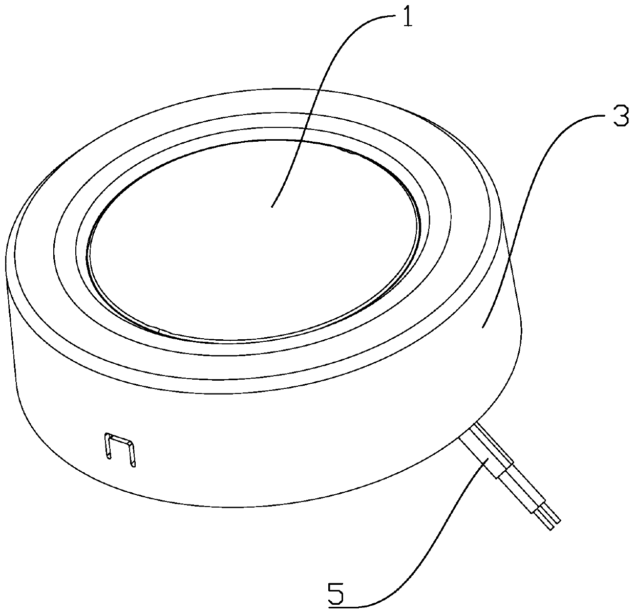
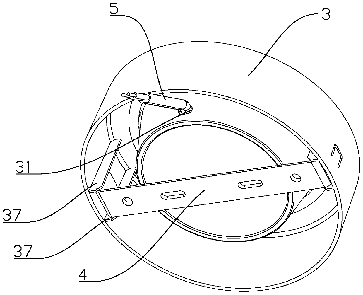
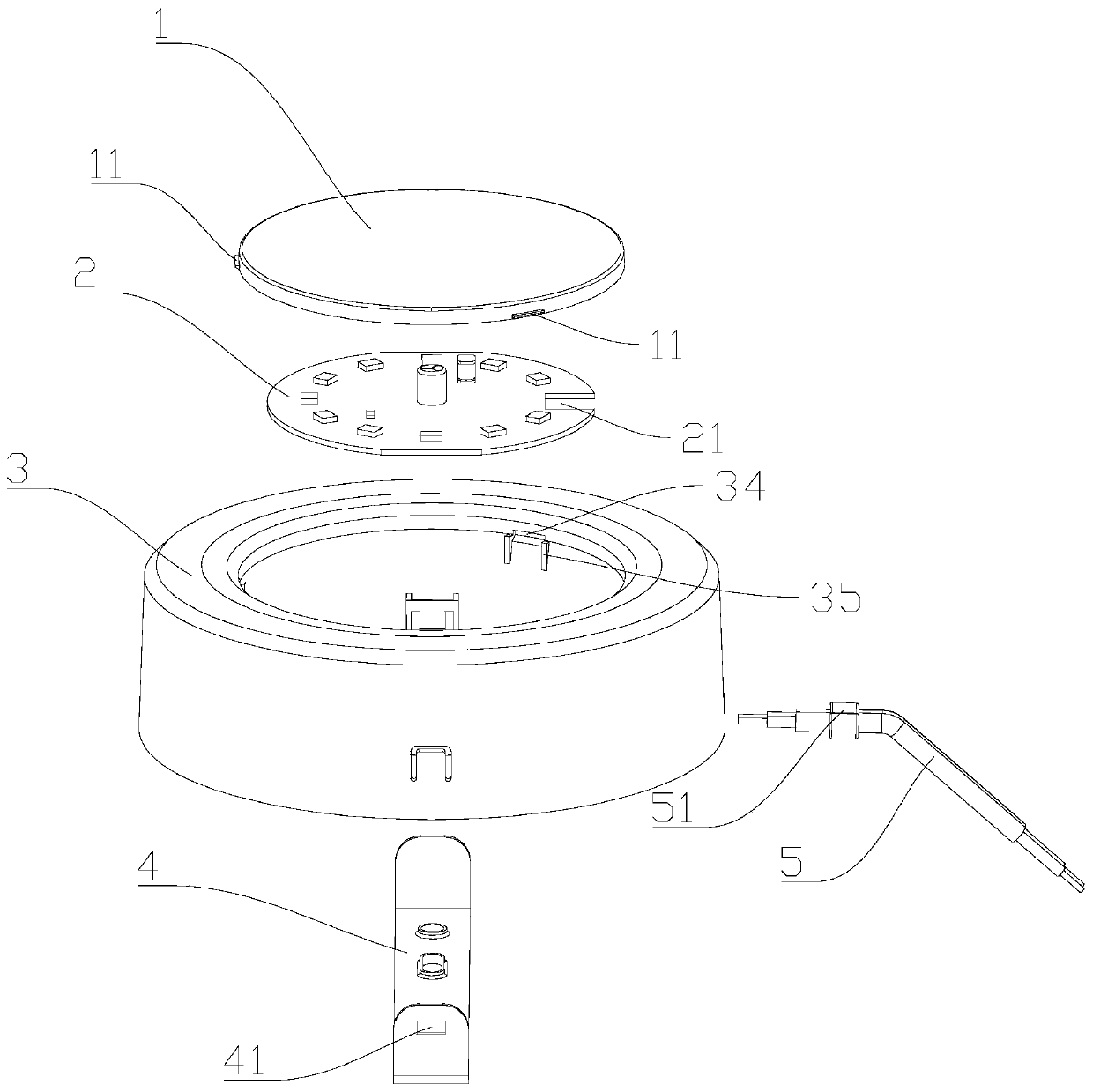
LED surface-mounted down lamp

A surface-mounted tube and lamp body technology, which is applied in lighting devices, fixed lighting devices, lighting auxiliary devices, etc., can solve the problems of good heat dissipation, high assembly cost, and high material cost of die-casting aluminum lamp housings, and solve the cost of molds and material cost, convenient and simple assembly, and simple preparation process

Pending Publication Date: 2020-08-04
中山市木林森健康照明科技有限责任公司
View PDF0 Cites 0 Cited by
  • Summary
  • Abstract
  • Description
  • Claims
  • Application Information

AI Technical Summary

Problems solved by technology

Plastic-clad aluminum lamp housings are rare in the market, mainly due to the high mold process requirements and high production costs of plastic-clad aluminum lamp housings. The price is not as cheap as full-plastic lamp housings, and the heat dissipation is not as good as die-cast aluminum lamp housings The heat dissipation of the lamp housing is good, so there are few in the market
Die-casting aluminum lamp housing is an aluminum lamp housing made by die-casting process. Although the heat dissipation is good, the production cost of die-casting process is high, the investment in equipment is large, and the wall thickness of the workpiece is high, the material cost is high, and the light transmittance is not high; the whole piece Product assembly needs to be done with several screws, the assembly cost is high and the assembly process is cumbersome
The mold of the all-plastic bright light shell is simple, the light transmittance is very high, and the penetration rate in the market is very high, but the light source board and the bracket need to be fixed by screw posts, and the installation and disassembly are relatively troublesome

Method used


Image

  • LED surface-mounted down lamp
  • LED surface-mounted down lamp
  • LED surface-mounted down lamp

Examples


Embodiment Construction

[0029] The present invention will be described in further detail below with specific examples, but the present invention is not limited to the following specific examples.

[0030] In describing the present invention, it should be understood that the terms "center", "longitudinal", "transverse", "upper", "lower", "front", "rear", "left", "right", " The orientations or positional relationships indicated by "vertical", "horizontal", "top", "bottom", "inner" and "outer" are based on the orientations or positional relationships shown in the drawings, and are only for the convenience of describing the present invention and Simplified descriptions, rather than indicating or implying that the device or element referred to must have a particular orientation, be constructed and operate in a particular orientation, and thus should not be construed as limiting the invention. In addition, the terms "first", "second", etc. are used for descriptive purposes only, and should not be understoo...


PUM


Abstract

The invention discloses an LED surface-mounted down lamp, and relates to the technical field of down lamps, the surface-mounted down lamp comprises a lampshade, a light source plate, a lamp body, a sheath wire and a mounting bracket, wherein the lampshade, the light source plate, the sheath wire and the mounting bracket are all detachably mounted on the lamp body, and the sheath wire is electrically connected with the light source plate. The LED lamp has the beneficial effects that the lampshade, the light source plate, the sheath wire, the mounting bracket and the lamp body are all of a detachable buckle structure, no screw structure is adopted, the assembly is very convenient and simple, the assembly efficiency can be improved, and the cost can be reduced. When the down lamp needs to bedismounted, only the buckles need to be opened, dismounting is convenient and easy, and the structure of the down lamp cannot be damaged. Moreover, the lamp body and the mounting bracket are made of plastic, so that the manufacturing cost is low, the preparation process is simple, and the problems of mold cost and material cost can be solved.

Description

technical field [0001] The invention relates to the technical field of downlights, in particular to an LED surface-mounted downlight. Background technique [0002] LED surface-mounted downlight is a product improved and developed on the basis of traditional downlights using new LED lighting sources. Compared with traditional downlights, it has the following advantages: energy saving, low carbon, long life, good color rendering and fast response speed, and LED downlights The design of the lamp is more beautiful and light, and the overall unity and perfection of the architectural decoration can be maintained during installation, and the perfect unity of the ceiling art will not be destroyed because of the setting of the lamp, so it is more and more popular among people. [0003] There are three main types of lamp housings for LED surface-mounted downlights on the market: plastic-clad aluminum type, die-cast aluminum type, and full-plastic type. Plastic-clad aluminum lamp hous...

Claims


Application Information

Patent Timeline
IPC IPC(8): F21S8/00F21V17/10F21V19/00F21V21/10F21Y115/10
CPCF21S8/00F21V17/104F21V19/001F21V21/10F21Y2115/10
Inventor 黄琦李稔江忠平章建波罗丽光陈华
Owner 中山市木林森健康照明科技有限责任公司
Features
  • R&D
  • Intellectual Property
  • Life Sciences
  • Materials
  • Tech Scout
  • Unparalleled Data Quality
  • Higher Quality Content
  • 60% Fewer Hallucinations
Learn More