
Clothes hanger production device

A production device and hanger technology, applied in the field of automation, can solve the problems of low efficiency and achieve high efficiency and good fixing quality

Active Publication Date: 2020-08-07
台州市牛诺电子商务有限公司
View PDF12 Cites 0 Cited by
  • Summary
  • Abstract
  • Description
  • Claims
  • Application Information

AI Technical Summary

Problems solved by technology

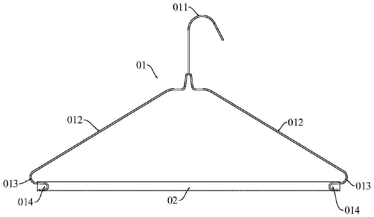
At present, the wire frame 01 can be formed by machine, but the fixing operation between the wire frame 01 and the pipe fitting 02 needs to be done manually, and the efficiency is low

Method used


Image

  • Clothes hanger production device
  • Clothes hanger production device
  • Clothes hanger production device

Examples


Embodiment Construction

[0032] The present invention will be further described below in conjunction with the accompanying drawings.

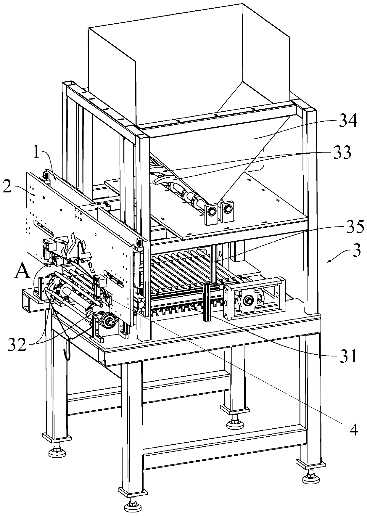
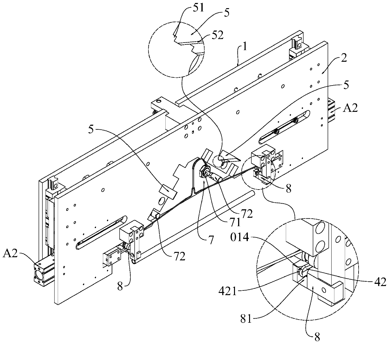
[0033] as attached figure 2 The shown hanger production device includes a first base 1, a lifting plate 2, a pipe separation and positioning device 3 and a pipe clamping device 4; image 3 with attached Figure 4 As shown, the first base 1 is fixed; the lifting plate 2 can move up and down relative to the first base 1, and its lifting is driven by the first cylinder A1; the pipe fitting separation and positioning device 3 can separate the pipe fittings 02 one by one Separated and transported to the clamping station for positioning; two clamping devices 4 are symmetrically installed on the lifting plate 2 .

[0034] as attached Figure 5 As shown, the tube clamping device 4 includes two symmetrically arranged sliding tables 41, wherein each of the sliding tables 41 is equipped with a tube clamping knife 42 and a spreader 43, wherein: the sliding table 41 can be posi...


PUM


Abstract

The invention discloses a clothes hanger production device, which comprises a first base, a lifting plate, a pipe fitting separating and positioning device, pipe clamping devices, a steel wire frame manufacturing mold and a steel wire frame feeding device, wherein the first base is fixedly arranged; the lifting plate can do lifting motion relative to the first base, and the lifting of the liftingplate is driven by a first air cylinder; the pipe fitting separating and positioning device can separate the pipe fittings one by one and convey the pipe fittings to a clamping station for positioning; the two pipe clamping devices are symmetrically mounted on the lifting plate; and the steel wire frame feeding device is used for transferring the steel wire frame manufactured by the steel wire frame manufacturing mold to the lifting plate. The clothes hanger production device can automatically assemble and fix the steel wire frame and the pipe fitting, and is high in efficiency and good in fixing quality.

Description

[0001] This application is a divisional application of an invention patent with application number 201910701476.0 and an application date of July 31, 2019, entitled "A Clothes Hanger Production Device and Method". technical field [0002] The invention relates to the technical field of automation, in particular to a clothes hanger production device. Background technique [0003] as attached figure 1 The clothes hanger shown includes a wire rack 01 and a pipe fitting 02. The wire rack 01 includes a hook body part 011, two extension parts 012 extending from the hook body part 011 to both sides, and the ends of the extension parts are bent inward. The bent arc-shaped turning part 013 and the clamping part 014 extended from the turning part 013, that is, the wire frame 01 has two clamping parts 014, and the two clamping parts 014 are respectively clamped on the two sides of the pipe fitting 02. inside the hole. The clothes hanger is generally used for hanging clothes with high...

Claims


Application Information

Patent Timeline
Patent Type & Authority Applications(China)
IPC IPC(8): A47G25/28B23P19/00
CPCA47G25/28B23P19/00
Inventor 蔡桂平
Owner 台州市牛诺电子商务有限公司
Learn More