Metal component flaw detection screening equipment

A technology for screening equipment and metal parts, applied in the field of metal parts flaw detection and screening equipment, can solve the problems of reducing production efficiency, slow detection speed, and inability to efficiently achieve synchronization of production and detection, and achieve the effect of speeding up production efficiency and reducing scrap rate

Inactive Publication Date: 2020-08-07
福州经济技术开发区米达尔科技有限公司
View PDF0 Cites 0 Cited by
  • Summary
  • Abstract
  • Description
  • Claims
  • Application Information

AI Technical Summary

Problems solved by technology

[0002] At present, with the development of society, in the processing of parts, it is necessary to provide real-time process quality control for raw materials, semi-finished products, finished products, and product components, especially to control the metallurgical quality and production process quality of product materials, and the quality information that passes the inspection can be fed back For the design and process department, it can improve the design and manufacturing process to improve product quality, reduce waste and repaired products, reduce manufacturing costs, and improve production efficiency. Among them, non-destructive testing is to inspect the inspected parts without damaging the working state of the workpiece or raw materials. A test method to check the surface and internal quality of components plays an important role in the quality assurance system, but the existing detection method is to spot check individual parts, which cannot guarantee the quality of all parts, and the detection speed is slow and cannot be efficient The realization of production detection synchronization reduces production efficiency

Method used


Image

  • Metal component flaw detection screening equipment
  • Metal component flaw detection screening equipment
  • Metal component flaw detection screening equipment

Examples


Embodiment Construction

[0014] All features disclosed in this specification, or steps in all methods or processes disclosed, can be combined in any way, except for mutually exclusive features and or steps.

[0015] Combine below Figure 1-4 The present invention is described in detail, and for convenience of description, the orientations mentioned below are now stipulated as follows: figure 1 The up, down, left, right, front and back directions of the projection relationship itself are the same.

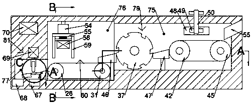
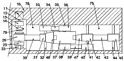
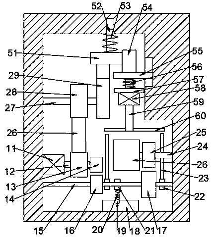
[0016] A flaw detection and screening device for metal parts of the device of the present invention includes a body 10, a conveying chamber 75 is provided in the body 10, a detection chamber 76 is provided on the left side of the conveying chamber 75, and a classification chamber is provided on the left side of the detection chamber 76. cavity 77, a power cavity 78 is provided on the rear side of the detection cavity 76, an analysis system 70 is fixed on the left side of the body 10, a hydraulic pump 69 is...


PUM


Abstract

The invention discloses metal component flaw detection screening equipment. A machine body is included and internally provided with a conveying cavity. The left side of the conveying cavity is provided with a detection cavity. A classification cavity is formed in the left side of the detection cavity. A power cavity is formed in the rear side of the detection cavity. An analysis system is fixedlyarranged on the left side of the machine body. A hydraulic pump is fixedly arranged on the lower side of the analysis system. An inlet is fixedly formed in the right side of the machine body. A wastecavity and a finished product cavity are fixedly formed in the lower side of the classification cavity. A detection device for ultrasonic detection is arranged in the power cavity and comprises a mainmotor fixedly arranged on the rear side wall of the power cavity. The main motor is in power connection with a motor shaft. The equipment can automatically achieve batched component detection and classification, detection is finished during component production, detecting and machining are synchronous, the production efficiency can be improved, and the component rejection rate is reduced.

Description

technical field [0001] The invention relates to the field of crack detection, in particular to a metal part flaw detection and screening equipment. Background technique [0002] At present, with the development of society, in the processing of parts, it is necessary to provide real-time process quality control for raw materials, semi-finished products, finished products, and product components, especially to control the metallurgical quality and production process quality of product materials, and the quality information that passes the inspection can be fed back For the design and process department, it can improve the design and manufacturing process to improve product quality, reduce waste and repaired products, reduce manufacturing costs, and improve production efficiency. Among them, non-destructive testing is to inspect the inspected parts without damaging the working state of the workpiece or raw materials. A test method to check the surface and internal quality of co...

Claims


Application Information

Patent Timeline
Patent Type & Authority Applications(China)
IPC IPC(8): B07C5/34B07C5/02B07C5/36
CPCB07C5/02B07C5/34B07C5/361B07C5/362
Inventor 马文冲
Owner 福州经济技术开发区米达尔科技有限公司
Why Eureka
Try Eureka