Temperature controller automatic assembling machine

A temperature controller and assembly machine technology, applied in assembly machines, metal processing, metal processing equipment and other directions, can solve the problems of low degree of automation, difficult quality control, low production efficiency, etc., to improve product quality and production efficiency, improve The effect of the level of assembly automation

Pending Publication Date: 2020-08-07
CIXI CITY KADA THERMOSTAT
0 Cites 2 Cited by

AI-Extracted Technical Summary

Problems solved by technology

[0003] At present, in the production and manufacturing process of the thermostat, each processing procedure is an independent procedure, and each independent procedure uses a single device for semi-automatic manual operation. The accuracy of this single device is poor, and the product yield ...

Abstract

The invention relates to a temperature controller automatic assembling machine. The temperature controller automatic assembling machine comprises a frame, a base plate, a rotary table, a motor, a servo rotating shaft station, a knob insulator installation station between a leaf spring and a bimetal, a limit piece clamping installation station, a pressure limit piece and adjusting shaft internal knob insulator installation station, a gluing station, a screw station, a finished product laying-off station and an inferior-quality product sorting station, the frame is a cube structure of which an upper part is opening, and the base plate is fixed at a top part of the frame; the rotary table is rotationally arranged on the base plate through the motor; several temperature controller bottom diesfor placing a temperature controller are evenly arranged on the rotary table along a peripheral direction of the rotary table; and the servo rotating shaft station, the knob insulator insulation station between the leaf spring and the bimetal, the limit piece clamping installation station and the pressure limit piece and adjusting shaft internal knob insulator installation station are mounted at periphery of the rotary table clockwise or anticlockwise. The invention aims at providing a temperature controller automatic assembling machine for making up a blank of a temperature controller assembling machine in the market.

Application Domain

Assembly machinesMetal working apparatus

Technology Topic

Electric machineryServo +2

Image

  • Temperature controller automatic assembling machine
  • Temperature controller automatic assembling machine
  • Temperature controller automatic assembling machine

Examples

  • Experimental program(1)

Example Embodiment

[0032] The present invention will be further described below with reference to specific embodiments, but the present invention is not limited to these specific embodiments. Those skilled in the art should realize that the present invention covers all alternatives, modifications and equivalents that may be included within the scope of the claims.
[0033] In the description of the present invention, it should be noted that, for orientation words, such as the terms "center", "horizontal", "longitudinal", "length", "width", "thickness", "upper", "lower" , "Front", "Back", "Left", "Right", "Vertical", "Horizontal", "Top", "Bottom", "Inside", "Outside", "Clockwise", "Counterclockwise" ” etc. indicating the orientation and positional relationship are based on the orientation or positional relationship shown in the accompanying drawings, which are only for the convenience of describing the present invention and simplifying the description, rather than indicating or implying that the device or element referred to must have a specific orientation or a specific orientation. The structure and operation should not be construed as limiting the specific protection scope of the present invention.
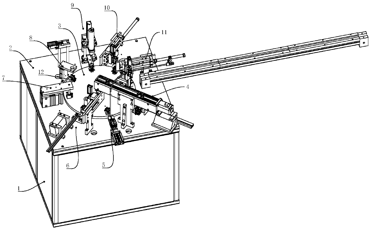
[0034] like figure 1 As shown, an automatic thermostat assembly machine is shown, including a frame 1, a base plate 2, a turntable 3, a motor (not shown), a servo rotating shaft station 4, and a porcelain rice installation station between the shrapnel and the double gold. , Limit piece clamping installation station 6, pressing the limit piece and adjusting the inner ceramic rice installation station 7, glue station 8, screw station 9, finished product blanking station 10 and defective sorting station 11. The rack 1 is a cube structure with an open top, the bottom plate 2 is fixed on the top of the rack 1 ; the turntable 3 is rotatably arranged on the bottom plate 2 by the motor; the turntable 3 A plurality of thermostat bottom molds 12 for placing thermostats are evenly arranged along the circumferential direction of the turntable 3; The limit piece clamping and installation station 6 and the pressure limit piece and the porcelain rice installation station 7 in the adjustment shaft are installed on the periphery of the turntable 3 clockwise or counterclockwise.
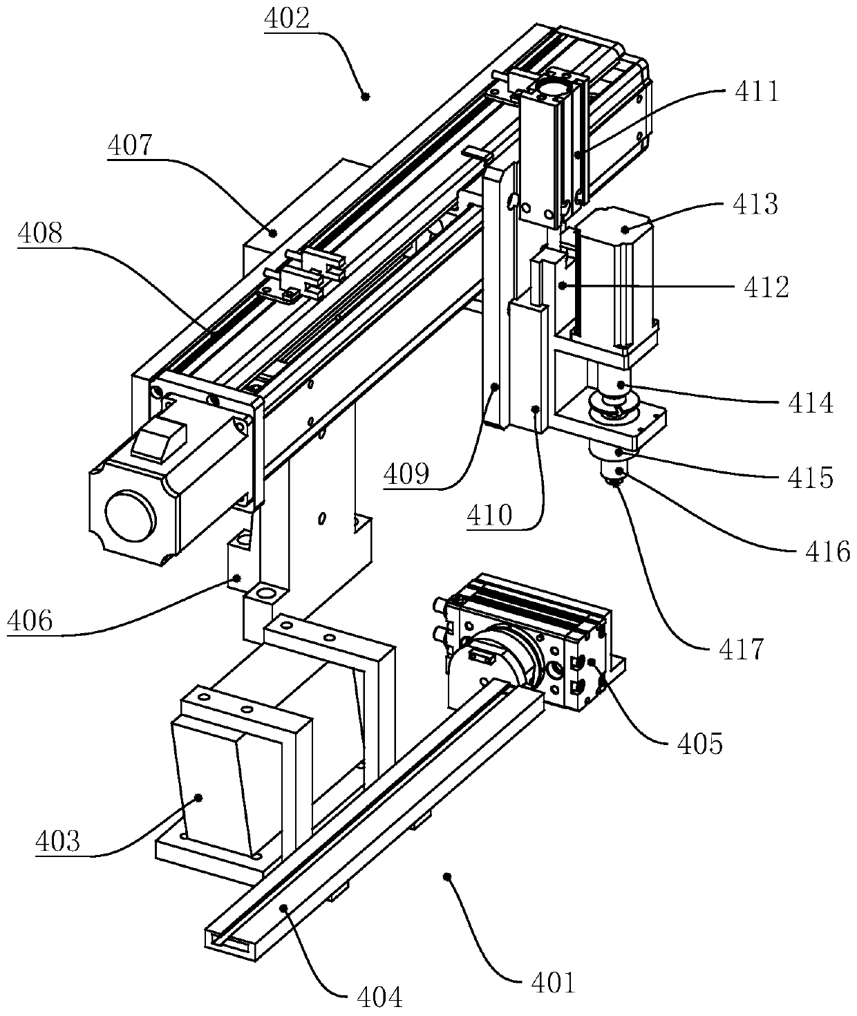
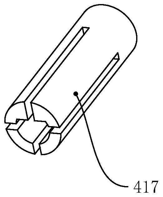
[0035] like figure 2 , 3 As shown, the servo rotating shaft station 4 includes a rotating shaft feeding device 401 and a rotating shaft assembling device 402; the rotating shaft feeding device 401 includes a first vibrating body 403, a rotating shaft channel 404 fixedly connected with the first vibrating body 403, and a rotating shaft Cylinder 405, the rotating shaft is sent to the rotating cylinder 405 through the rotating shaft flow channel 404; the rotating shaft assembling device 402 includes a locking shaft supporting frame 406, a locking rotating shaft fixing frame 407, and is fixed on the locking rotating shaft fixing frame 407 The belt conveyor 408, the lifting fixed plate 409, the first lifting guide 410, the first linear cylinder 411, the torsion shaft slider 412, the rotating motor 413, the coupling 414, the rotating rod 415, the rotating shaft 416 and the rotating shaft clamp 417, the lock shaft support frame 406 is fixed on the base plate 2, the lock shaft fixing frame 407 is fixed on the base plate 2 and is fixedly connected with the lock shaft support frame 406, the belt conveyor 408 It is fixed on the locking shaft fixing frame 407 through the sliding table bottom plate 2, the lifting fixing plate 409 is fixed on the slider of the belt conveyor, the first lifting guide rail 410 and the first linear cylinder 411 are fixed on the lifting fixing plate 409, the torsion shaft sliding block 412 cooperates with the first lifting guide 410 and is connected with the output end of the first linear cylinder 411, and the rotating motor 413 is fixed on the On the torsion shaft slider 412, the rotating rod 415 is connected to the rotating motor 413 through the coupling 414, the rotating shaft 416 is fixedly connected to the rotating rod 415, and the rotating shaft clip 417 is fixed on the inside the rotating rod 415.
[0036] like Figure 4-7 As shown, the ceramic rice installation station 5 between the shrapnel and the double metal includes a ceramic rice feeding device 501 and a porcelain rice assembling device 502, and the porcelain rice feeding device 501 includes a feeding pipe 503, a feeding block 504 and a feeding Cylinder 505; the feeding block 504 has a channel for conveying the porcelain rice inside, and one end of the channel of the feeding block 504 is connected to the external porcelain rice feeding vibrating plate, and the other end is located above the porcelain rice assembling device 502; The feeding cylinder 505 is located above the feeding block 504 and the output end of the feeding cylinder 505 faces the channel of the feeding block 504; the porcelain rice assembling device 502 includes a pushing cylinder 506, a displacement block 507, Centralizing cylinder 508, clamping block 509, blocking block 510 and blocking cylinder 511; the pushing cylinder 506 is fixed on the bottom plate 2, and one side of the displacement block 507 is fixedly connected to the output end of the pushing cylinder 506 , the other side is fixed with the centering cylinder 508, the output end of the centering cylinder 508 is fixedly connected with the clamping block 509, the blocking cylinder 511 is fixed above the clamping block 509, and the blocking block 510 It is fixedly connected with the output end of the blocking cylinder 511 ; the front end of the clamping block 509 has a circular hole structure 512 for clamping the ceramic rice, and the circular hole structure 512 is driven by the centering cylinder 508 to clamp or loosen ; The clamping block 509 is composed of a first clamping block 513 and a second clamping block 514, and the rear ends of the first clamping block 513 and the second clamping block 514 are provided with The connecting hole 515 connected to the output end of the centralizing cylinder 508, and the front ends of the first clamping block 513 and the second clamping block 514 are close to the second clamping block 514 and the first clamping block 513. The first extension portion 516 and the second extension portion 517 are formed by partially extending forward for a certain distance, and a semicircular hole structure 512 is correspondingly provided between the first extension portion 516 and the second extension portion 517 and forms the Circular hole structure 512 .
[0037] like Figure 8 , 9 As shown, the position 6 for clamping and installing the limit piece includes a limit piece feeding device 601 and a first manipulator 602. The limit piece feeding device 601 includes a second vibrating body 603 and the second vibrating body 603 The fixedly connected limiter runner 604 , the limiter dislocation block 605 located at the end of the limiter runner 604 , the limiter incoming sensing piece 606 fixed on the limiter dislocation block 605 , and The limit piece brake 607, the limit piece dislocation block 605 is fixed on the bottom plate 2; the first manipulator 602 includes a manipulator support plate 608, a displacement support plate 609, a first displacement fixing block 610, and a second displacement fixing block 610. block 611, first guide rod 612, second guide rod 613, displacement slide block 614, second lift guide rail 615, second linear cylinder 616, lift slide block 617, grab block 618 and first mini cylinder 619; the The manipulator support plate 608 is fixed on the bottom plate 2, the displacement support plate 609 is laterally fixed on the manipulator support plate 608, and the first displacement fixing block 610 and the second displacement fixing block 611 are respectively fixed on the Both ends of the displacement support plate 609, the displacement sliding block 614 is slidably arranged on the first displacement fixing block 610 and the second displacement fixing block 610 through the first guide rod 612 and the second guide rod 613. Between blocks 611, the output end of the first mini cylinder 619 is connected to the displacement sliding block 614, the second lifting guide 615 is fixed on the displacement sliding block 614, and the second linear cylinder 616 is fixed on the displacement sliding block 614. On the second lifting guide rail 615, the lifting sliding block 617 cooperates with the second lifting guide rail 615 and the lifting sliding block 617 is connected to the output end of the second linear cylinder 616; the grab block 618 is fixed On the lifting slider 617 , a limiting piece clip 620 is arranged below the grabbing block 618 .
[0038] like Figure 10 As shown, the porcelain rice installation station in the adjustment shaft of the pressure-limiting tablet machine includes a porcelain rice lifting cylinder 701, a porcelain rice lifting block 702 and a porcelain rice lifting pipe 703, and the porcelain rice lifting block 702 and the porcelain rice lifting The output end of the air cylinder 701 is connected, and the porcelain rice lifting tube 703 is fixed under the porcelain rice lifting block 702 .
[0039] like Figure 11 As shown, the gluing station 8 includes a gluing fixing block 801, a gluing support plate 802 and a gluing cylinder 803, the gluing fixing block 801 is fixed on the bottom plate 2, and the gluing cylinder 803 is fixed On the gluing fixing block 801 , the gluing support plate 802 is connected to the output end of the gluing cylinder 803 .
[0040] like Figure 12 , 13 As shown, the screw station 9 includes a screw feeding device 901 and a screw assembling device 902. The screw feeding device 901 includes a support rod 9001, a dislocation guide rail 9002, a dislocation slider 903, a dislocation cylinder 904 and a blanking block 905; The dislocation guide rail 9002 is fixed on the top of the support rod 9001, the dislocation slider 903 is slidingly matched with the dislocation guide rail 9002, and one end of the dislocation slider 903 is connected to the output end of the dislocation cylinder 904; The cylinder 904 is fixed on one end of the dislocation guide rail 9002; the blanking block 905 is fixed on the dislocation guide rail 9002 and is located above the dislocation slider 903; the dislocation guide rail 9002, the dislocation slider 903 and all the The blanking blocks 905 are provided with through holes from top to bottom; the screw assembly device 902 includes a locking screw plate 906, two locking screw seats 907, a second mini cylinder 908, two linkage plates 909, two The guide shaft 910, the linear bearing 911 and the electric screwdriver 912, the locking screw plate 906 is fixed on the bottom plate 2, the two locking screw seats 907 are respectively fixed on the top and bottom of the locking screw plate 906, two The guide shafts 910 are arranged parallel to each other between the two locking screw seats 907 , the second mini cylinder 908 is fixed on the top of the locking screw plate 906 , and the output end of the second mini cylinder 908 is linked with the The plate 909 is fixedly connected, the linkage plate 909 can move vertically with the two guide shafts 910 through the linear bearing 911 , and the electric screwdriver 912 is fixedly connected to the linkage plate 909 .
[0041] like Figure 14As shown, the finished product blanking station 10 includes a second manipulator 101 and a material frame (not shown). The difference between the second manipulator 101 and the first manipulator 602 is that the second manipulator 101 uses fingers An air cylinder replaces the gripping block 618 of the first robot 602 .
[0042] like Figure 15 As shown, the defective sorting station 11 includes a third manipulator 111 and a conveyor belt 112 , and the structure of the third manipulator 111 is the same as that of the second manipulator 101 .
[0043] The working principle of the thermostat automatic assembly machine of this embodiment:
[0044] 1. Semi-finished product placement station: put the semi-finished product from the grating detection area into the bottom mold 12 of the thermostat and then enter the next station.
[0045] 2. Servo rotating shaft station: the rotating shaft is fed by the rotating vibrating feeding plate, and then enters the rotating cylinder 405 through the rotating shaft flow channel 404. The rotating cylinder 405 acts to send the rotating shaft to the rotating shaft clamp 417, and the rotating cylinder 405 resets; The rotating shaft of the conveyor 408 is translated to the top of the thermostat bottom mold 12, and then the first linear cylinder 411 acts to lower the rotating shaft into the thermostat bottom mold 12, and the rotating motor 413 starts to twist the shaft. If there is a defective product in the process of twisting the shaft, the divider will continue to operate, but the remaining stations will stop working until the defective product is sorted out at the defective product sorting station; if there is no defective product in the process of twisting the shaft, it will go to the next process. go in.
[0046] 3. The working method of the porcelain rice installation station between the shrapnel and the double gold: the porcelain rice enters the feeding channel of the feeding block 504 from the external porcelain rice feeding vibrating plate, and the porcelain rice moves along the feeding cylinder 505 under the action of the feeding cylinder 505. The unloading pipe 503 moves toward the porcelain rice assembling device 502. When the porcelain rice incoming sensor (not shown) located above the unloading block 905 detects the porcelain rice, the information is sent to the PLC control system, and the PLC control system controls the blocking The air cylinder 511 is opened to ensure that only one grain of porcelain rice is supplied at a time. The ceramic rice enters the circular hole structure 512 of the clamping block 509 under the action of the feeding cylinder 505. After the optical fiber detection sensor detects the ceramic rice entering the circular hole structure 512, the information is sent to the PLC control system. PLC control The system controls the pusher cylinder 506 to start working, the pusher cylinder 506 drives the centering cylinder 508 to enter the 12th station of the thermostat bottom mold, and then the centering cylinder 508 releases the porcelain rice, and the porcelain rice enters the hole of the bimetal sheet, Next, the centering cylinder 508 is then opened to ensure that the extension part does not contact the metal sheet of the thermostat, the pushing cylinder 506 is retracted, and the whole set of operations is completed.
[0047] 4. The limit piece clamping and installation station: the limit piece is fed by the limit piece vibrating feeding tray, and enters the limit piece dislocation block 605 through the limit piece flow channel 604, and the second lifting cylinder drives the clamping block to carry out Reset after clipping. The first mini-cylinder 619 moves, reaches the top of the bottom mold 12 of the thermostat, and starts to rise and fall, placing the limiting piece on the semi-finished product.
[0048] 5. The ceramic rice installation station in the adjustment shaft of the pressure limit tablet machine: the porcelain rice is divided by the porcelain rice vibrating feeding plate one by one into the porcelain rice lifting tube 703. The porcelain rice lifting cylinder 701 starts to act, and drives the porcelain rice lifting tube 703 to squeeze the limit piece.
[0049] 6. Gluing station: After the bottom mold 12 of the thermostat reaches above the glue station 8, the glue cylinder 803 starts to act after the movement reaches the lifting and moving point, and the glue cylinder 803 resets after the glue is finished.
[0050] 7. Screw station: First, the screws are separated into the screw feeding mechanism by the external screw feeding vibrating plate. After the high-precision optical fiber sensor senses the screws, the feedback signal is sent to the PLC control system. The PLC control system controls the dislocation cylinder 904 start working. The dislocation cylinder 904 drives the dislocation sliding block 903 so that the through holes on the dislocation sliding block 903 communicate with the through holes on the blanking block 905 and the dislocation guide rail 9002 . After the through holes are connected, the screws are driven along the feeding tube to the installation station. After the operation of the misaligned cylinder 904 is completed, it returns to the initial position. When the start signal of the screw installation station is turned on, the lift cylinder starts to rise out of the first section. After reaching the designated position, the screw quickly enters the screw chuck, and the lift cylinder starts to rise out of the second section. The electric screwdriver 912 starts to start, and the lift cylinder returns to the initial position one second after the action is completed. At this point, the assembly process of the screw is completed.
[0051] 8. Finished product station: the finished product is lifted and lowered, and the second manipulator 101 picks the finished product from the bottom mold 12 of the thermostat and puts it into the material box.
[0052] 9. Defective product sorting station: the third manipulator 111 takes out the defective product from the bottom mold 12 of the thermostat, and sends it away through the conveyor belt 112 .
[0053] It can be understood that the PLC control system in this embodiment and the connection or control between the PLC control system and each sensor and each cylinder are in the prior art.
[0054] It should be understood by those skilled in the art that the above description and the embodiments of the present invention shown in the accompanying drawings are provided by way of example only and do not limit the present invention. The functional and structural principles of the present invention can be arbitrarily modified without departing from the principles shown above.

PUM

no PUM

Description & Claims & Application Information

We can also present the details of the Description, Claims and Application information to help users get a comprehensive understanding of the technical details of the patent, such as background art, summary of invention, brief description of drawings, description of embodiments, and other original content. On the other hand, users can also determine the specific scope of protection of the technology through the list of claims; as well as understand the changes in the life cycle of the technology with the presentation of the patent timeline. Login to view more.

Similar technology patents

Pre-drying heating device for rotary screen printing machine

ActiveCN109237904AImprove production efficiency and product qualityGood drying efficiency
Owner:ZHEJIANG MIZUDA TEXTILE PRINTING & DYEING TECH CO LTD

Classification and recommendation of technical efficacy words

Why Eureka
Try Eureka