
Mechanical finger based on magnetorheology, and mechanical finger drive method

A mechanical finger and magneto-rheological technology, applied in the direction of manipulators, program-controlled manipulators, manufacturing tools, etc., can solve the problems of easily damaged objects, poor protection effect of mechanical fingers, poor gripping stability of mechanical fingers, etc.

Inactive Publication Date: 2020-08-07
CHONGQING UNIV
View PDF6 Cites 3 Cited by
  • Summary
  • Abstract
  • Description
  • Claims
  • Application Information

AI Technical Summary

Problems solved by technology

Specifically, the mechanical finger in the existing solution uses the spring piece as the contact end directly in contact with the target, and the magnetorheological fluid is used as the power to drive the deformation of the spring piece, so that in the actual use process, the existing mechanical finger has the following Problem: 1) The spring sheet is easy to deform, and there is no stable clamping shape and state, making it difficult to firmly clamp the target with a certain weight, resulting in the problem of poor clamping stability of the mechanical finger; 2) In the existing scheme, the target is clamped by the piston rod pushing the spring leaf to deform, and the actual contact between the spring leaf and the target is a "bump" structure at the abutting position of the piston rod, that is, there is a "bump" between the spring leaf and the target object. Point contact” state (the contact area is very small), on the one hand, the “point contact” method is more likely to damage the target (the target is locally stressed), which leads to the problem of poor protection effect of the existing mechanical fingers. On the one hand, the "point contact" method makes the target object easy to shake during the transfer process, which also leads to the problem of poor clamping stability of the mechanical fingers

Method used


Image

  • Mechanical finger based on magnetorheology, and mechanical finger drive method
  • Mechanical finger based on magnetorheology, and mechanical finger drive method
  • Mechanical finger based on magnetorheology, and mechanical finger drive method

Examples


Embodiment 1

[0045] This embodiment discloses a mechanical finger based on magnetorheology.

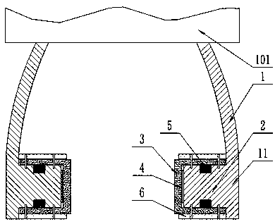
[0046] Such as figure 1 Shown: a mechanical finger based on magnetorheology, including a finger body 1, a drive unit for driving the finger body 1 to apply a clamping force to a target, and a control unit electrically connected to the drive unit;

[0047] The clamping part 11 of the finger body 1 has a contact end facing the target and used to contact the target when in use; the position of the contact end is fixed with a magnetorheological elastic part 3 covering the end surface of the contact end; the magnetorheological elastic part 3 There is a gap fit between the side facing the contact end and the end face of the contact end, and a pressure sensing component 4 connected to the control unit signal is correspondingly provided in the gap between the magneto-rheological elastic part 3 and the contact end; the clamping part 11 An electromagnetic coil assembly 5 electrically connected to the contr...


PUM

PropertyMeasurementUnit
Coercivityaaaaaaaaaa

Abstract

The invention relates to the technical field of mechanical fingers, and specifically relates to a mechanical finger based on magnetorheology, and a mechanical finger drive method. The mechanical finger comprises a finger body, a drive unit and a control unit, wherein a clamping part of the finger body is provided with a contact end which faces a target object during use and is used for making contact with the target object; a magnetorheological elastic part covering the end surface of the contact end is fixedly arranged at the position of the contact end; one side facing the contact end, of the magnetorheological elastic part, forms clearance fit with the end surface of the contact end, and a pressure sensing assembly is correspondingly arranged in a gap between the magnetorheological elastic part and the contact end; and an electromagnetic coil assembly is further arranged at a position corresponding to the magnetorheological elastic part, on the clamping part. The invention further discloses a mechanical finger drive method. The mechanical finger based on magnetorheology, and the mechanical finger drive method are capable of giving consideration to both clamping stability and a protection effect on the target object.

Description

technical field [0001] The invention relates to the technical field of mechanical fingers, in particular to a magnetorheological-based mechanical finger and a driving method for the mechanical finger. Background technique [0002] With the continuous improvement of people's living standards, more and more tasks are replaced by robots. The robotic arm is one of them. One of the tasks of using the robotic arm is to grab the target. The object contact is the end effector installed on the robotic arm, and the most common end effector is the robotic finger. In actual work, the targets grasped by the robotic fingers are not only static, but also include many dynamic targets, even targets with particularly high speeds. In actual work, the existing mechanical fingers are not flexible and have no active stiffness adaptability, so that when facing static or dynamic targets, the mechanical fingers are easy to pinch the surface of the operating object, or the clamping is unstable. [...

Claims


Application Information

Patent Timeline
IPC IPC(8): B25J15/12B25J9/16B25J15/00B25J19/02
CPCB25J9/1612B25J15/0023B25J15/12B25J19/02
Inventor 王牛李小龙陈冠印况飞陈鹏举
Owner CHONGQING UNIV
Learn More