Anti-reverse tooling for lifting station and anti-reverse method thereof

A technology of tooling and limit pins, which is applied in the direction of hoisting devices, springs/shock absorbers, vibration suppression adjustments, etc., and can solve the problem that the equipment cannot be dropped in one direction

Active Publication Date: 2021-11-26
HEFEI HUILIPU MOTOR
View PDF7 Cites 0 Cited by
  • Summary
  • Abstract
  • Description
  • Claims
  • Application Information

AI Technical Summary

Problems solved by technology

[0004] In order to solve the technical problem that the existing anti-reverse tooling of the lifting force station cannot fall in one direction after the motor is hoisted and the power is off, the present invention provides an anti-reverse tooling of the lifting force station and its anti-reverse method

Method used


Image

  • Anti-reverse tooling for lifting station and anti-reverse method thereof
  • Anti-reverse tooling for lifting station and anti-reverse method thereof
  • Anti-reverse tooling for lifting station and anti-reverse method thereof

Examples


Embodiment 1

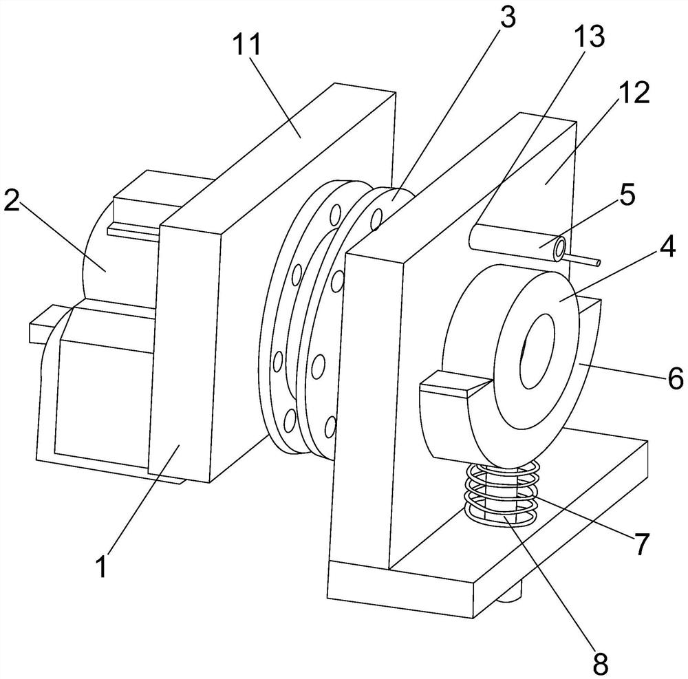
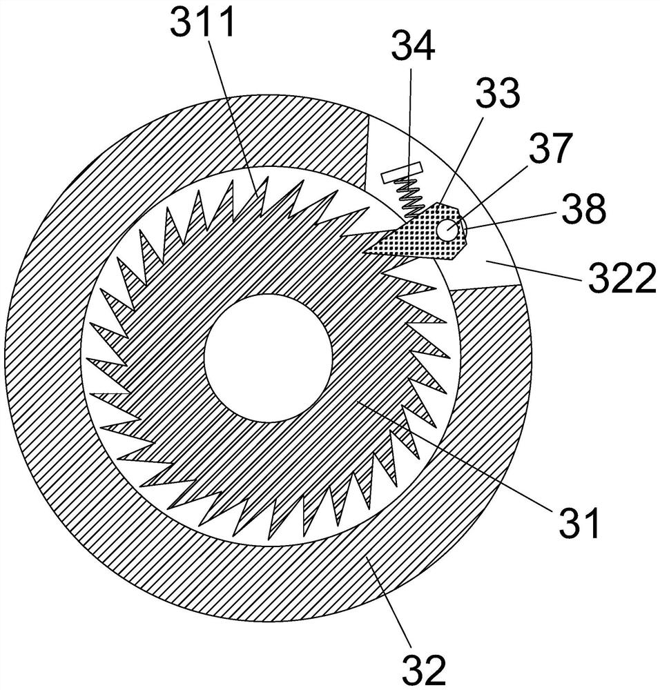
[0056] see figure 1 , figure 2 as well as image 3 , this embodiment provides an anti-reversal tooling for a lifting station, the tooling includes a base 1, a motor 2, a lifting plate 3 and a one-way bearing 4, and may also include a positioning pin 5, a positioning component 6, a shock absorber Spring 7 and limit bar 8. Among them, the base 1, the motor 2 and the one-way bearing 4 can all use existing related components, that is, the tooling of this embodiment can be modified, added or replaced on the basis of the existing tooling.

[0057] In this embodiment, the base 1 includes a first mounting block 11 and a second mounting block 12 . There is an installation space for accommodating the rotation of the suspension force plate 3 between the first installation block 11 and the second installation block 12 . Motor 2 is installed on the installation block one 11, and one-way bearing 4 is installed on the installation block two 12. Both the first installation block 11 and ...

Embodiment 2

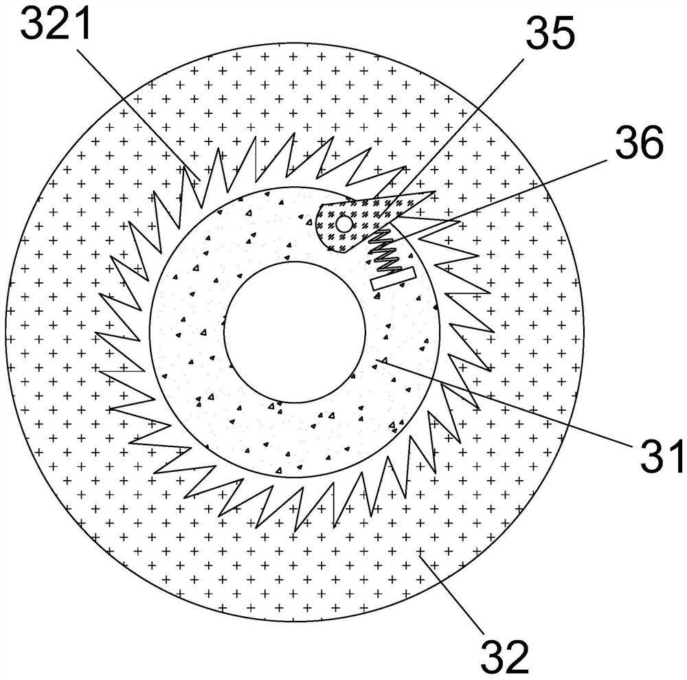
[0079] This embodiment provides an anti-reversal tooling for the lifting force station, which is similar to the tooling of Example 1, the difference is that there are more than one set of limiting pins 2 35 and elastic members 2 36 of the limiting component 2, the minimum for two groups. In this embodiment, each limiting pin 2 35 and its adjacent elastic member 2 36 are set as a group of connection assemblies, and the arrangement of each group of connecting assemblies is the same as that of the limiting pin 2 35 and the elastic member in Embodiment 1. Two 36 are set in the same way, so that when the motor 2 rotates forward, multiple sets of connecting components can provide a more stable driving effect, especially when one of the two limit pins 35 breaks down, other limit pin two 35 can still play a role to the effect. In this way, on the one hand, the anti-rotation can be ensured, and on the other hand, the connection between the inner disc 31 and the outer disc 32 can be ma...

Embodiment 3

[0081] This embodiment provides a lifting station anti-reversal tooling, which is similar to the tooling of Example 1, the difference is that the positioning part 6 in this embodiment is a magnetic structure, that is, a magnetic ring, which can be connected with the one-way bearing 4 The outer ring is magnetically adsorbed. At the same time, only the outer ring of the one-way bearing 4 can be attracted to the positioning component 6 , and other structures cannot be attracted to the positioning component 6 . In this way, the positioning component 6 can conveniently fix the outer ring of the one-way bearing 4 so that the outer ring cannot rotate.


PUM


Abstract

The invention discloses an anti-reverse tooling of a lifting station and an anti-reverse method thereof. The anti-reverse tooling of the lifting station includes a base, a motor, a lifting plate and a one-way bearing, and the lifting plate includes an inner plate, an outer plate, a limit assembly 1, a limit assembly 2, and a control unit. The inner disc is sleeved on the output shaft of the motor, and the inner ring of the one-way bearing is connected with the inner disc shaft. The inner disc is provided with a plurality of barbs 1, and the outer disc is provided with a plurality of barbs 2, and has a groove structure for winding external wires. The first limiting component includes a limiting pin one, an elastic member one and a telescopic component, and the second limiting component includes a second limiting pin and an elastic member two. The control unit judges whether the motor is in a power-off state, and if so, drives the free end of the limit pin 1 to break away from the notch 1 in the axial direction; otherwise, drives the free end of the limit pin 1 to abut in the notch 1 in the axial direction. The present invention can avoid the situation that one-way cannot fall while anti-reversing, facilitates the lifting work of the tooling, and improves the use range and safety of the tooling.

Description

technical field [0001] The invention relates to an anti-reverse tooling in the technical field of lifting force tooling, in particular to an anti-reverse tooling for a lifting force station, and also relates to an anti-reverse method comprising a plurality of the anti-reverse tooling. Background technique [0002] Hoisting refers to the general term for the installation and positioning of equipment by cranes or hoisting mechanisms. In the process of overhaul or maintenance, various hoisting tools are used to lift equipment, workpieces, appliances, materials, etc. to change their positions. The hoisting system is an important machine and equipment. The commonly used hoisting methods include cantilever hoisting, installation beam hoisting, cable hoisting, floating crane hoisting, etc. [0003] The lifting tool is usually composed of a base, a motor, a lifting plate, etc. The motor rotates to drive the lifting plate to rotate, and the lifting wire will be wound on the lifting p...

Claims


Application Information

Patent Timeline
Patent Type & Authority Patents(China)
IPC IPC(8): B66D1/12B66D1/28B66D1/54B66D1/56F16F15/067
CPCB66D1/12B66D1/28B66D1/54B66D1/56B66D2700/0183F16F15/067
Inventor 蓝小荔童立飞吴招军陈志伟李强冯广伟
Owner HEFEI HUILIPU MOTOR
Why Eureka
Try Eureka