Reciprocating hydraulic diaphragm pump

A hydraulic diaphragm pump, reciprocating technology, applied in the field of reciprocating pumps, can solve the problems of large structure, many failure points, heavy weight, etc., and achieve the effect of obvious structural advantages, improved plunger stroke, and compact structure

Pending Publication Date: 2020-08-07
SHENYANG DOUBLE RING PUMP CO LTD
View PDF0 Cites 0 Cited by
  • Summary
  • Abstract
  • Description
  • Claims
  • Application Information

AI Technical Summary

Problems solved by technology

Now the three-plunger structure is more used. When the viscosity of the conveying medium is high, the operating speed is low, and its structure is huge, complex, very heavy, expensive, and has many failure points.
At the same time, more waste will be generated, causing environmental pollution

Method used


Image

  • Reciprocating hydraulic diaphragm pump
  • Reciprocating hydraulic diaphragm pump
  • Reciprocating hydraulic diaphragm pump

Examples


Embodiment 1

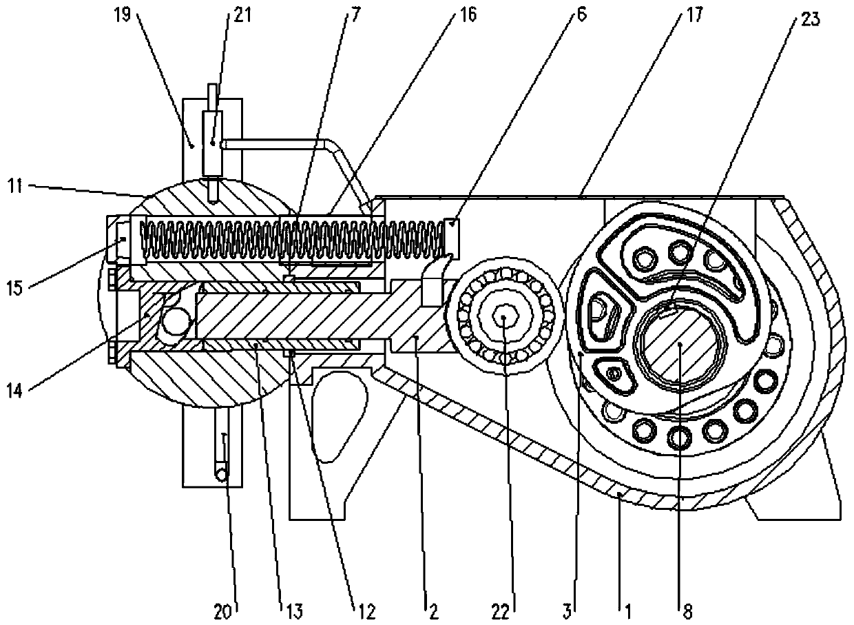
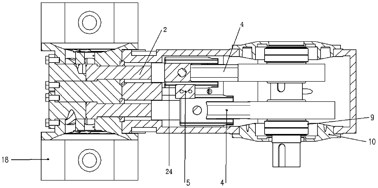
[0023] Such as figure 1 and figure 2 As shown, a reciprocating hydraulic diaphragm pump consists of a transmission case 1, a plunger 2, an involute cam 3, a plunger bearing 4, a guide frame 5, a retaining column 6, a return spring 7, a mandrel 8, and a bearing 9. Bearing gland 10, hydraulic chamber assembly 11, positioning sleeve 12, cylinder liner 13, front plug 14, spring gland 15, spring sheath 16, cover plate 17, diaphragm head assembly 18, valve group 19, oil supply line 20. Oil return pipeline 21, bearing pin 22, key 23 and other main components.

[0024] The hydraulic chamber assembly 11 is positioned in cooperation with the transmission case 1 through the positioning sleeve 12, the hydraulic chamber assembly 11 is filled with hydraulic oil, and the diaphragm head assembly 18 is arranged on both sides of the hydraulic chamber assembly 11, arranged back to back. A cylinder liner 13 is installed in the hydraulic chamber assembly 11, and the cylinder liner 13 is compres...


PUM


Abstract

The invention discloses a reciprocating hydraulic diaphragm pump. The reciprocating hydraulic diaphragm pump comprises a transmission box body, a plunger piston, a hydraulic cavity assembly, a diaphragm head assembly, an oil refill pipeline, and an oil return pipeline; a cylinder sleeve is installed in the hydraulic cavity assembly; the plunger piston is installed in the cylinder sleeve; a plungerpiston bearing is installed at the tail end of the plunger piston via a bearing pin; the plunger piston bearing is in contact with involute cams; the involute cams are connected with a mandrel; a bumping post is arranged on the plunger piston; the bumping post is connected with one end of a return spring; and the other end of the return spring is connected with a spring pressing cover. In the process of operation of the provided diaphragm pump, the distance between the plunger piston and an axes is equal to the base circle radius of the involute cams, so during working, the plunger piston bears no other lateral force other than gravity and therefore the phenomenon of eccentric wear does not occur. When the involute cams push the plunger piston to move forward, the plunger piston makes uniform linear motion, and the two cams are arranged to form a 180 degree angle, so medium can be continuously transported at uniform velocity, and stable pressure can be generated without the addition of an energy accumulator to a pipeline.

Description

technical field [0001] The invention relates to the field of reciprocating pumps, in particular to a reciprocating hydraulic diaphragm pump. Background technique [0002] Most of the existing reciprocating pumps are driven by a crankshaft or an eccentric block, which form a sinusoidal pulsation curve during operation. The pulsation is very large, and the strength of the cylinder body is high, so it is necessary to increase the material to ensure the strength. At the same time, buffer devices such as accumulators need to be installed on the pipeline. [0003] The crankshaft of the reciprocating pump rotates once, and the crosshead and the plunger are pushed and pulled by the connecting rod to reciprocate for one circle. There will be three collisions, one is the crosshead hitting the crosshead slideway, the second is the crosshead pin and the connecting rod, and the third is Where the crankshaft and connecting rod collide, noise and vibration are generated by the collision ...

Claims


Application Information

Patent Timeline
Patent Type & Authority Applications(China)
IPC IPC(8): F04B43/067F16H25/14
CPCF04B43/067F16H25/14
Inventor 姜新喜白士莹范丘林韩立国冷严昊张亚光
Owner SHENYANG DOUBLE RING PUMP CO LTD
Why Eureka
Try Eureka